
Page 14 - manuscript_ijb05583
P. 14
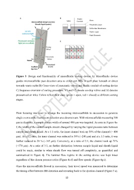
Figure  3:  Design  and  functionality  of  microfluidic  sorting  device  A)  Microfluidic  device

               guides microscaffolds past detection area to either sort BBs in well plate beneath or direct
               towards waste outlet B) Cross-view of pneumatic valves and fluidic conduit of sorting device

               C) Sequence overview of sorting procedure. V1 and V2 denote on-chip valves and AI denotes

               pressurized air inlet. Colors reflect their state (green = open, red = closed) at different sorting
               stages.


               Flow focusing was used to  arrange the incoming microscaffolds  in  succession to  generate
               single events at the fluorescent detection area downstream. With microscaffolds measuring 300

               µm in diameter, a sample stream width of around 400 µm was targeted. As seen in Figure 4a-

               f, the width of the central sample stream changed by varying the liquid pressure ratio between
               sample and sheath liquid. At a 1:1 ratio, the inner channel took up 50% of the channel (~ 400

               µm). At a 1:2 ratio, the inner channel was reduced to 30% (~240 µm) and at a 1:3 ratio, it was
               further reduced to 20 % (~165 µm). Conversely, at a ratio of 2:1, the channel took up 71%

               (~570 µm). At a ratio of 3:1, no further distinction between sample liquid and sheath liquid
               could  be made, similar to  when sheath  flow was turned off  completely, as  quantified  and

               summarized  in  Figure  4j.  The  laminar  flow  regime  in  the  sorting  device  was  kept  intact

               regardless of the chosen pressure ratios (Figure 4a-f) and flow speeds (Figure 4g-i).

               Once the microscaffolds flowed in succession, their travel speed was measured to determine

               the timing offset between BB detection and rerouting back to the ejection channel (Figure 3 a).


                                                           13