
Page 54 - AIH-1-4
P. 54
Artificial Intelligence in Health A fuzzy system for heartbeat classification
(150 ms). At first, the signal is analyzed using high values Using neural networks and customized learning rules
of the two thresholds. The low thresholds are used for the to reduce error, ANFIS modifies the Sugeno inference
case of no QRS detection; here, a search-back technique system’s settings. One potential set of rules is shown in
is used to refer to the previous time for the QRS complex Equations XIII and XIV for a fuzzy system with two inputs
(Figures 3 and 4). 13,28 (x and y), one output (z), and a fuzzy inference Sugeno
Once the features are extracted, ANFIS is applied. model.
The fuzzy rules between a set of inputs and outputs are Rule 1: If x is equal to A , y is equal to B then, f 1= p1 x+q1 y+r1
1
1
generated by the Sugeno fuzzy model. The proposed (XIII)
ANFIS operates like a fuzzy inference system (FIS) and Rule 2: If x is equal to A , y is equal toB then, f2=p x+q
produces fuzzy rules and membership functions (MFs), y+r 2 2 2 (XIV) 2
with its output described by Equation XII: 2
The fuzzification, rule, normalization, defuzzification,
n ())() and summing layers make up the five layers of the Sugeno
i
L (∏ j =1 MF x j z
γ= ∑ (XII) ANFIS network model. The degree of membership is
())
(
L
= i 1 ∑∏ n MF x determined for each input and the adaptive node represents
= i 1 = j 1 j the first layer (Equation XV).
where the membership function is denoted by MF, the
j input is x (j = 1, 2,…, n), and the output of the j fuzzy O 1, i= = µ x () = exp − ( xc− i 2 (XV)
th
th
)
j
rule is z . i A i a i
Figure 3. Block diagram of pan-Tompkins algorithm
27
Abbreviation: ECG: Electrocardiogram.
A B
C D
E F
G H
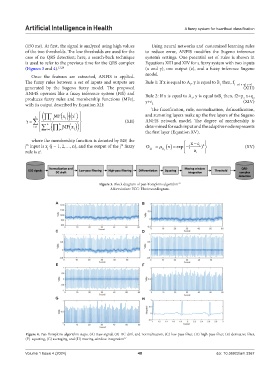
Figure 4. Pan-Tompkins algorithm steps. (A) Raw signal, (B) DC drift and normalization, (C) low-pass filter, (D) high-pass filter, (E) derivative filter,
(F) squaring, (G) averaging, and (H) moving-window integration 27
Volume 1 Issue 4 (2024) 48 doi: 10.36922/aih.3367