Page 192 - AJWEP-22-6
P. 192

Tsankov, et al.

                                                                    height, and the shortest bracket length and lowest slope
                                                                    angle, while ensuring compliance with the requirements
                                                                    of the given lighting class.
                                                                       For the project in Pavlikeni and Byala Cherkva, where
                                                                    the  spacing  between  poles  (luminaire)  is  fixed,  a  non-
                                                                    standard optimization problem must be defined to determine
                                                                    the lowest luminaire power, combined with the lowest pole
                                                                    height and smallest bracket tilt angle that together satisfy the
                                                                    requirements of the designated lighting class.
                                                                       The formulation of the optimization problem, where
                                                                    the  pole  spacing  is  fixed  and  the  luminaire  power,
                                                                    mounting height, and tilt angle are optimized to meet
                                                                    the requirements of a given M-class according to EN
                                                                    13201, is as follows:

                                                                    2.2.2.1. Given (parameters)
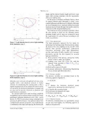
                Figure 7. Light distribution of a street light-emitting   The listed parameters  represent  the key inputs for
                diode luminaire, type 1                             optimizing road lighting design: Road geometry defines
                                                                    the layout of the street lighting system, the EN 13201
                                                                    lighting  class  specifies  performance  requirements
                                                                    (luminance,  uniformity, glare, edge illumination),
                                                                    and the road surface R-table, together with luminaire
                                                                    photometry, provide the data  required  for accurate
                                                                    lighting calculations.
                                                                    (i)  Road geometry: Pole spacing, carriageway width,
                                                                        number of lanes, curbs, and medians.
                                                                    (ii)  Lighting class under EN 13201: M , with the
                                                                                                          k
                                                                        required  limits  specified  in  Table  2—L , U , ,
                                                                                                                  o req
                                                                                                             req
                                                                        U , , TI , and EIR .
                                                                         l req
                                                                                         req
                                                                               max
                                                                    (iii) Road surface type and R-table.
                                                                    (iv) Luminaire  photometry  (Illuminating  Engineering
                                                                        Society-format light distribution file).
                                                                    2.2.2.2. Decision variables
                Figure 8. Light distribution of a street light-emitting   The  decision  variables  are  calculated  based  on  the
                diode luminaire, type 2                             following equation (Equation I):

                                                                           P H,)
                old poles were removed and replaced with new ones,     x  (,                                      (I)
                together with a new electrical network.  A  further   where:
                rationale for maintaining the existing poles is that a   (i)  P  denotes the  luminaire  electrical  power
                significant proportion of the reinforced concrete poles   (equivalently, luminous flux/dimming level).
                are owned by the electricity distribution company and
                are also used to provide electricity to domestic and   (ii)  H signifies the mounting height.
                small business consumers.                           (iii) θ represents the luminaire tilt angle.
                  For standard optimization tasks involving completely   (iv) Domain constraints are
                new lighting systems, and in accordance with the two energy   P[ P , P  ],  H [ H  , H  ],  [  ,  ]
                performance indicators introduced in EN 13201—power       min  max         min  max        min  max
                density (D  [W/m ]), and annual energy consumption per   2.2.2.3. Objective function
                               2
                         P
                unit area (D  [kWh/m /year])—the optimal solution from   To minimize installed power (or, equivalently, energy
                                  2
                          E
                a technical and economic perspective was sought through   use per  unit  road  length),  the  following  equation  is
                a combination of the largest pole spacing, the smallest pole   employed (Equation II):
                Volume 22 Issue 6 (2025)                       186                           doi: 10.36922/AJWEP025310242
   187   188   189   190   191   192   193   194   195   196   197