
Page 174 - AJWEP-v22i3
P. 174
Mounira
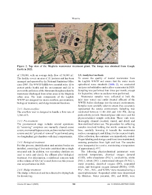
Figure 2. Top view of the Maghnia wastewater treatment plant. The image was obtained from Google
Earth in 2022.
of 150,000, with an average daily flow of 30,000 m . 2.5. Analytical methods
3
The facility covers an area of 11 hectares and has been To assess the quality of treated wastewater from
managed and operated by the National Sanitation Office the Lagfafe WWTP and ensure that the water meets
since 2003. The WWTP fulfills two essential roles: (i) to agricultural reuse standards (Table 2), we conducted
protect public health and the environment and (ii) to analyses on both inflow and outflow wastewater in 2020.
prevent the pollution of the Hammam Boughrara dam by Sampling was performed four times per month, except
wastewater discharged from urban areas in the Maghnia for September, when no analyses were performed.
urban area. The main components of the Lagfafe Wastewater samples were collected at both the
WWTP are designed for storm overflow, pre-treatment, inlet (raw water) and outlet (treated effluent) of the
biological treatment, and sludge treatment functions. WWTP, before discharge into the natural environment.
Samples were carefully taken to ensure they accurately
2.4.1. Storm overflow represented the source environment. Sampling was
The overflow weir is designed to handle a flow rate of conducted between 11:00 AM and 1:00 PM, during
3,266 m /h. peak activity periods. Standard glass vials were used for
3
physicochemical sample collection. These vials were
2.4.2. Pre-treatment thoroughly cleaned (washed, rinsed, and dried) and
The pre-treatment stage includes several operations: then sterilized before use. The procedure for collecting
(i) “screening” comprises one manually cleaned coarse samples involved holding the sterile container by its
screen, one manual bypass screen, and two mechanized fine base, carefully lowering it beneath the wastewater
screens and (ii) “grit and oil removal” is performed using surface, uncapping it, and filling it to the required depth.
two longitudinal grit chambers with dual compartments. After collection, the container was immediately sealed.
Proper labeling and storage conditions were maintained,
2.4.3. Biological treatment ensuring protection from light and heat. The samples
For this process, denitrification and aeration basins are were transported in a cooler, maintaining a temperature
installed, consisting of four units combined into a single of approximately 4°C.
structural unit. In addition, two secondary clarifiers are The following physicochemical parameters were
used to settle and clarify the effluent after biological analyzed: temperature, chemical oxygen demand
treatment. For chlorination, a reinforced concrete tank (COD), ortho-phosphates (PO 4 ), conductivity, nitrite
3−
−
with a volume of 826.5 m is used; however, this process (NO 2 ), nitrate (NO₃⁻), ammoniacal nitrogen (N-NH₄⁺),
3
was not performed in 2020. water potential, dissolved oxygen (DO), suspended
solids, and biological oxygen demand (BOD 5 ). COD,
2.4.3. Sludge treatment PO 4 , NO 2 , NO 3 , and N-NH₄⁺ were measured using a
−
−
3−
The sludge is thickened and then directed to drying beds spectrophotometer. Suspended solids were determined
for dewatering. by filtration. Water potential, DO, and BOD 5 were
Volume 22 Issue 3 (2025) 168 doi: 10.36922/AJWEP025120085