
Page 96 - ESAM-1-2
P. 96
Engineering Science in
Additive Manufacturing Impact of machine factors on PBF part surface quality
and International Standardization Organization (ISO) a rotating hatch angle of 67°, whereas the laser beam focus
3252:2023, with a particle size distribution of 10 – 45 μm. diameter was 80 – 115 μm. The substrate plate was pre-
Its mass density is 8.0 g/cm . Its chemical composition is heated to 200°C before starting the fabrication process.
3
shown in Table 1. The powder was dried before loading During the fabrication process, its gas flow came from
into the PBF machine with professional dry bags (Nikon right to left, and the recoating direction came forward and
SLM Solutions AG, Germany) to ensure that the relative backward (Figure 2). High-purity argon gas was pumped
humidity of the powder was <10% before starting the PBF into the build chamber to maintain oxygen level below
process. 1,000 ppm throughout the fabrication process. Argon gas
An AM machine was used for the PBF process (SLM280 flow speed was controlled at 22 m/s to ensure that heavy
Twin 700W laser, Nikon SLM Solutions, Germany). spattering and soot formed from the rapid melting process
A powder layer thickness of 30 μm was maintained, with could be effectively removed from the powder bed. The
oxygen level was closely monitored via the AM system’s
monitoring control system to ensure that the oxygen level
was below 1,000 ppm. The metal powder was spread onto
the substrate plate evenly with the calibrated recoater. The
gap between the recoater blade and the substrate plate was
controlled at 200 μm to ensure consistency across build
jobs. Steel substrate plates were also ground smoothly, with
their Ra <30 μm, to ensure that the building of the first
layer on the substrate plate was smooth.
2.2. Design of parts
In this study, the testing parts in Figure 3 were produced
and measured for their surface quality. Each part consisted
of a 25 × 25 × 10 mm cube with a 25 mm diameter, 10 mm
3
high cylinder on top. Twenty parts were produced per plate.
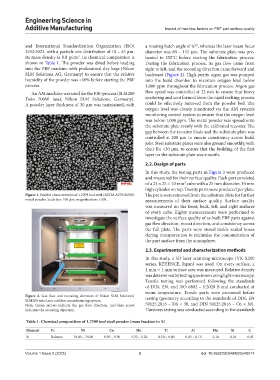
Figure 1. Powder characteristics of 1.2709 tool steel (ASTM A276/M300) The parts were removed from the substrate plate for further
metal powder. Scale bar: 100 μm; magnification: ×100. measurements of their surface quality. Surface quality
was measured on the front, back, left, and right surfaces
of every cube. Eighty measurements were performed to
investigate the surface quality of as-built PBF parts against
gas flow direction, recoat direction, and consistency across
the full plate. The parts were stored inside sealed boxes
during transportation to minimize the contamination of
the part surface from the atmosphere.
2.3. Experimental and characterization methods
In this study, a 3D laser scanning microscope (VK-X200
series, KEYENCE, Japan) was used. On every surface, a
1 mm × 1 mm surface area was measured. Relative density
was determined by testing specimens using light microscopy.
Tensile testing was performed following the standards
of DIN, EN, and ISO 6892 – 1:2020 B and conducted at
room temperature. Tensile parts were processed before
Figure 2. Gas flow and recoating direction of Nikon SLM Solutions’ testing (geometry according to the standards of DIN, EN
SLM280 twin laser additive manufacturing system.
Note: Green arrows indicate the gas flow direction, and blue arrow 50125:2016 – D6 × 30, and DIN 50125:2016 – C6 × 30).
indicates the recoating direction. Hardness testing was conducted according to the standards
Table 1. Chemical composition of 1.2709 tool steel powder (mass fraction in %)
Element Fe Ni Co Mo Ti Al Mn Si C
% Balance 18.00 – 19.00 8.50 – 9.50 4.70 – 5.20 0.50 – 0.80 0.05 – 0.15 0.10 0.10 0.03
Volume 1 Issue 2 (2025) 3 doi: 10.36922/ESAM025240014