
Page 99 - ESAM-1-2
P. 99
Engineering Science in
Additive Manufacturing Impact of machine factors on PBF part surface quality
elliptical. This would result in reduced energy density, thus When all identical parts with the same geometry design
causing higher Ra or even forming porosity inside the part and the same support design were fabricated inside the
due to a lack of fusion. Figure 8 illustrates the consequence same build chamber, using the same argon gas settings,
of such laser interaction due to the position of the parts. recoating settings, metal powder, and process parameters,
When the laser was shot directly onto the powder bed from their Ra varied across the full substrate plate. The key
90° vertically, the melt pool and laser spot size were nearly factors that account for such variations are the distance
a perfect round shape. However, when the part moved from the parts to the gas flow outlet and the center of the
away from the center of the laser spot, the melt pool shape laser spot. For example, parts 1, 8, and 13 had the worst Ra
became distorted, which negatively affected the surface because they were furthest away from the gas flow outlet,
quality of the as-built parts. as well as the center of the laser spot. On the other hand,
parts 5, 7, 11, 14, 16, 17, and 18 had better Ra because these
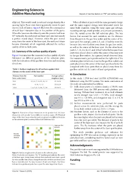
3.5. Summary of the surface quality of parts
parts were placed close to either the center of the laser spot
Figure 9 summarizes the measured surface quality of parts or the gas flow outlets. As a general trend observed from
fabricated on different positions of the substrate plate, the measurements, parts positioned on the right side of the
with the indication of the gas flow direction and recoating substrate plate (which are closer to the gas flow outlet) and
directions. parts placed near the center of the laser spot have better Ra
compared with those parts that are placed away from the
Table 5. Surface roughness for all surfaces against their gas flow outlet and the center of laser spot position.
distance to the center of the laser spot
4. Conclusion
Distance from the Part number Average surface
laser center (mm) roughness (µm) In this study, 1.2709 tool steel (ASTM A276/M300) was
32.0 2, 3, 6, 7, 14, 15, 18, 19 21.3±3.0 fabricated using the PBF system. The main conclusions of
89.0 9, 10, 11, 12 23.3±2.0 the study are summarized as follows:
122.6 1, 4, 5, 8, 13, 16, 17, 20 23.5±5.5 (i) Fully dense parts of a relative density of 99.9% were
fabricated from the PBF process with platform pre-
heating. Without heat treatment, its as-built ultimate
A B tensile strength was 1,135 ± 75 MPa, yield strength
was 915 ± 120 MPa, and elongation was 12 ± 3 %. It
has HV10 at 339 ± 35.
(ii) Surface measurements were performed for parts
placed across the substrate plate, and the average Ra
for as-built vertical walls was 22.6 ± 11.9 μm.
(iii) Machine factors, such as the distance of parts to the
Figure 8. Illustration of laser interaction on the powder bed. (A) Laser
interaction with powder bed at different incident angles. (B) Elliptical gas flow outlet, impact the Ra of as-built parts. The Ra
shape of the laser beam when the parts are placed at a different location becomes higher when the parts are placed further away
on the substrate plate (courtesy Nikon SLM Solutions AG). from the inert gas outlet. The distance of parts to the
center of the laser spot also impacts the Ra of as-built
parts. The Ra increases when the parts are placed
further away from the center of the laser spot location.
This study provides guidance and reference for
optimizing the PBF fabrication strategy, especially on the
part placement, considering machine factors such as inert
gas outlet and laser spot position.
Acknowledgments
The part fabrication work was supported by SLM Solutions
Figure 9. Surface roughness for all parts on the substrate plate. Singapore Pte Ltd. The metal powder was supported by
Notes: # indicates part number. The “X” mark in gray indicates the center SLM Solutions Singapore Pte Ltd.
of the laser spot. Green boxes indicate that produced parts have a good
Ra value smaller than 20 μm. Orange boxes indicate those produced parts Funding
have a relatively poor Ra value between 20 μm and 30 μm. Red boxes
indicate those produced parts have a poor Ra value larger than 30 μm. None.
Volume 1 Issue 2 (2025) 6 doi: 10.36922/ESAM025240014