
Page 85 - ESAM-1-4
P. 85
Engineering Science in
Additive Manufacturing TwinPrint: Dual-arm robotic bioprinting
saved z-height separately without readjusting the XY home a predictive machine learning model was developed as a
values. The arm travel speed can be adjusted using the axes software add-on to suggest optimal flow rates to the user
buttons, but this does not affect the 3D bioprinting velocity for the 3D bioprinting materials selected. This is detailed in
previously specified in the parsed G-code. another study. Moreover, to enhance user experience and
38
Analogs to the arms, to determine which Pump ease the printing process involving several components,
settings box corresponds to its respective pump set, only the side buttons offer device control both collectively and
one pump from each of the two sets can be initialized via individually.
the “Initialize” button. As shown in Figure 4B, Pump 1 is Finally, the “Printing Status monitoring” tab, as shown
the master pump while Pumps 2–4 are arranged according in Figure 3D, allows users to monitor the different printing
to their position from the master. Since a total of eight and pumping activities occurring across all devices
pumps can be connected to the TwinPrint GUI, a labeling collectively in a single tab, making it easier to quickly
feature is incorporated for easy reference to each pump discern any failure.
and its corresponding material type. This new name is
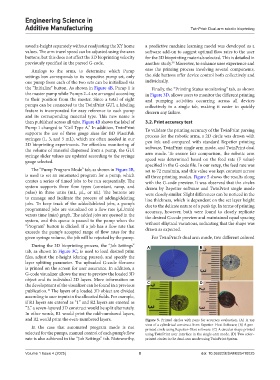
then published across all tabs. Figure 4B shows the label of 3.2. Print accuracy test
Pump 1 changed to “Cell Type A.” In addition, TwinPrint To validate the printing accuracy of the TwinPrint parsing
supports the use of three gauge sizes for BD PlastiPak process for the robotic arms, a 2D circle was drawn with
syringes (1, 3, and 5 mL), which are often needed in our
3D bioprinting experiments. For effortless monitoring of pen ink and compared with standard Repetier printing
the volume of material dispensed from a pump, the GUI software, TwinPrint single arm mode, and TwinPrint dual
arm mode. To ensure fair comparison, the robotic arm
syringe slider values are updated according to the syringe
gauge selected. speed was determined based on the feed rate (F value)
specified in the G-code file. In our setup, the feed rate was
The “Pump Program Mode” tab, as shown in Figure 3B, set to 72 mm/min, and this value was kept constant across
is used to set an automated program for a pump, which all three printing modes. Figure 5 shows the results along
creates a series of timed jobs to be run sequentially. The with the G-code preview. It was observed that the circles
system supports three flow types (constant, ramp, and drawn by Repetier software and TwinPrint single mode
pulse) in three units (mL, µL, or nL). The buttons are were closely similar. Slight differences can be noticed in the
to manage and facilitate the process of adding/deleting line thickness, which is dependent on the set layer height
jobs. To keep track of the added/deleted jobs, a pump’s due to the delicate nature of a pen’s tip. In terms of printing
programmed jobs are visualized on a flow rate (µL/min) accuracy, however, both were found to closely replicate
versus time (min) graph. The added jobs are queued in the the desired G-code preview and maintained equal spacing
system, and this queue is passed to the pump when the without elliptical variations, indicating that the shape was
“Program” button is clicked. If a job has a flow rate that drawn as expected.
exceeds the pump’s accepted range of flow rates for the
given syringe volume, the job will be rejected by the pump. For TwinPrint’s dual arm mode, two different colored
During the 3D bioprinting process, the “Job Settings” A B
tab, as shown in Figure 3C, is used to load desired print
files, adjust the z-height (during pauses), and specify the
layer splitting parameter. The uploaded G-code filename
is printed on the screen for user assurance. In addition, a
G-code visualizer allows the user to preview the loaded 3D
object and its individual 2D layers. More information on
the development of the visualizer can be found in a previous C D
10
publication. The layers of a loaded 3D object are divided
according to user inputs in the allocated fields. For example,
if R1 layers are entered as “1” and R2 layers are entered as
“2,” a seven-layered 3D construct would be split alternately.
In other words, R1 would print the odd-numbered layers,
and R2 would print the even-numbered layers. Figure 5. Printed circles with pens for accuracy evaluation. (A) A top
In the case that automated program mode is not view of a cylindrical construct from Repetier–Host Software; (B) A pen-
printed circle using Repetier–Host software. (C) A circular shape printed
selected for the pumps, manual control of each pump’s flow using TwinPrint user interface in the single-arm mode. (D) Two color–
rate is also achieved in the “Job Settings” tab. Noteworthy, printed circles in the dual-arm mode using TwinPrint System.
Volume 1 Issue 4 (2025) 8 doi: 10.36922/ESAM025410025