
Page 58 - GPD-2-4
P. 58
Gene & Protein in Disease K fragment for resistance gene hunting
0.2 cm electroporation cuvette and Ec2 program on to pUC19, MCS-free pUC19 (pUC19 -MCS ) formed white
MicroPulser Electroporator device (2.49 kV pulse) were colonies on AXI plate. This was related to the disruption of
-1
used (Bio-rad laboratories, Inc, USA). lacZalfa gene due to the removal of MCS. To confirm the
MCS removal, the plasmids isolated from transformants
2.9. Design of Promoter-RBS (Prom-RBS) sequence were cleaved by RsaI enzyme, ad pUC19 vector was used
E. coli-specific promoter was chosen and obtained from an as a control because one of the three restriction sites of
online resource (http://parts.igem.org) and the selected RsaI was found in MCS. Digestion of pUC19 with RsaI
[15]
17 base sequence contains constitutive and repetitive TA generated DNA fragments in three different sizes (241 bp,
sequence. As Shine-Dalgarno sequence, “TAAGGAGGT” 676 bp, and 1769 bp). The digestion of pUC19 -MCS with RsaI
was used and as a spacer, 6 bases, “ACAGCT,” were used. led to the formation of DNA fragments in two different
[16]
The sequences of Prom-RBS and primers used are listed in sizes (2010 bp and 676 bp) (Figure 2A). By referring to
Table 1. the patterns of DNA fragments yielded summarized in
Figure 2B, we could confirm the removal of MCS from the
3. Results vector.
3.1. K fragment 3.1.2. The construction of pKF
The Prom-RBS sequence and its structure are illustrated in Prom-RBS sequence designed for this study was introduced
Figure 1A and the schematic representation of K fragment with site-directed mutagenesis to the complementary strand
in Figure 1B. The K fragment contains a promoter and RBS and opposite direction of the bla gene in pUC19 -MCS to
TEM
at both ends. It was necessary to introduce an additional facilitate gene expression at both orientations. Three steps
RBS and promoter sequence, because the fragment with were involved in introducing the sequence due to its length.
resistance genes may be inserted in any sense which requires The workflow of these steps is illustrated in Figure 3A.
RBS and promoter for both orientations for expression of The PCR products produced during the site-directed
the cloned gene. A plasmid of K fragment (pKF) serving mutagenesis process are shown in Figure 3B. Briefly, PCR
as the template vector for K fragment was constructed. was performed using P1 and pUCPR as primers and the
The creation of K fragment entailed two processing steps: pUC19 -MCS vector as a DNA source. Then, the amplicon
(i) Derivation of multiple cloning site (MCS)-free pUC19 was used as a DNA source for the second PCR reaction
(pUC19 -MCS ), and (ii) construction of pKF vector. using P2 and pUCPR primers. The P2 primers contained a
part of the promoter and the RBS sequence that we wanted
3.1.1. Generation of pUC19 -MCS
to insert. This second amplicon was used as a DNA source
MCS was excised from the pUC19 vector using EcoRI and for third PCR reaction which was carried out using P3
HindIII, MCS was removed from pUC19 using these two primers containing the remaining part of the promoter
enzymes because their restriction sites are found at the ends and RBS sequence (Figure 3B). The final PCR product was
of MCS and are suitable for the cleaving of the entire MCS phosphorylated and self-ligated. The ligand was transferred
region. The cleaved DNA with the 5’ overhangs was blunted to E. coli DH10B, and the colonies grown on ampicillin-
with S1 Nuclease. The blunt-ended DNA fragments were containing agar were chosen for further investigations.
self-ligated and transferred into E. coli DH10B. Contrary Colony PCR was carried out using prmtrSeq and KsekF
A
B
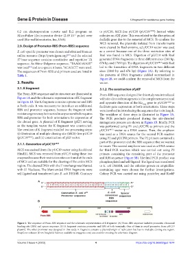
Figure 1. The sequence of Prom-RBS sequence and the schematic representation of K fragment. (A) Prom-RBS sequence includes promoter, ribosomal
binding site (RBS) and spacer sequence. (B) K fragment contains promoter and RBS at both terminals. One of them is ampR promoter, from pUC19
plasmid. The other promoter was designed in this study. K fragment contains a plasmid origin of replication but has no multiple cloning site region.
SnapGene software (from Insightful Science; available at snapgene.com) was used for creating the schematic diagram.
Volume 2 Issue 4 (2023) 4 https://doi.org/10.36922/gpd.1674