
Page 117 - GTM-4-3
P. 117
Global Translational Medicine Rapid diagnostic imaging on biopsy needle
A B
C D
E F
Figure 2. The CoreView imaging on needle prototype. The fixture
module, modeled in SolidWorks initially and fabricated using a three-
dimensional fused filament fabrication printer, features a structured
carbon polycarbonate frame and a custom microscope holder for
imaging core needle biopsies while still on the needle. The full prototype
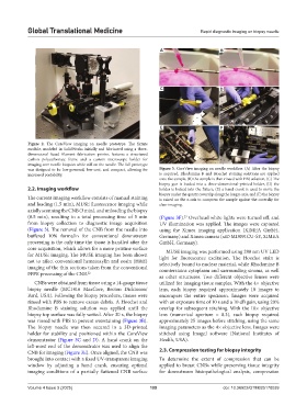
was designed to be low-powered, low-cost, and compact, allowing for Figure 3. CoreView imaging on needle workflow. (A) After the biopsy
increased portability. is acquired, Rhodamine B and Hoechst staining solutions are applied
onto the sample, (B) the sample is then rinsed with PBS solution, (C) The
biopsy gun is loaded into a three-dimensional-printed holder, (D) the
2.2. Imaging workflow holder is locked into the fixture, (E) a hand crank is used to move the
biopsy under the quartz coverslip along the long y-axis, and (F) the biopsy
The current imaging workflow consists of manual staining is raised on the z-axis to compress the sample against the coverslip for
and loading (1.5 min), MUSE fluorescence imaging while clear imaging.
axially scanning the CNB (3 min), and unloading the biopsy
(0.5 min), resulting in a total processing time of 5 min (Figure 3F). Overhead white lights were turned off, and
23
from biopsy collection to diagnostic image acquisition UV illumination was applied. The images were captured
(Figure 3). The removal of the CNB from the needle into using the Ximea imaging application (XIMEA GmbH,
buffered 10% formalin for conventional downstream Germany) and Ximea camera (xiD MD091CU-SY, XIMEA
processing is the only time the tissue is handled after the GmbH, Germany).
core acquisition, which allows for a more pristine surface
MUSE imaging was performed using 280 nm UV LED
for MUSE imaging. The MUSE imaging has been shown light for fluorescence excitation. The Hoechst stain is
not to affect conventional hematoxylin and eosin (H&E) selectively bound to nuclear material, while Rhodamine B
imaging of the thin sections taken from the conventional counterstains cytoplasm and surrounding stroma, as well
FFPE processing of the CNB. 22 as other structures. Two different objective lenses were
CNBs were obtained from tissue using a 14-gauge tissue utilized for imaging tissue samples. With the 4× objective
biopsy needle (MC1416 MaxCore, Becton Dickinson/ lens, each biopsy required approximately 10 images to
Bard, USA). Following the biopsy procedure, tissues were encompass the entire specimen. Images were acquired
rinsed with PBS to remove excess debris. A Hoechst and with an exposure time of 10 s and a 10 dB gain, using 20%
Rhodamine B staining solution was applied until the overlap for subsequent stitching. With the 10× objective
biopsy top surface was fully wetted. After 30 s, the biopsy lens (numerical aperture = 0.3), each biopsy required
was rinsed with PBS to prevent overstaining (Figure 3B). approximately 25 images before stitching, using the same
The biopsy needle was then secured in a 3D-printed imaging parameters as the 4× objective lens. Images were
holder for stability and positioned within the CoreView stitched using ImageJ software (National Institutes of
demonstrator (Figure 3C and D). A hand crank on the Health, USA).
left-most end of the demonstrator was used to align the
CNB for imaging (Figure 3E). Once aligned, the CNB was 2.3. Compression testing for biopsy integrity
brought into contact with a fixed UV-transparent imaging To determine the extent of compression that can be
window by adjusting a hand crank, ensuring optimal applied to breast CNBs while preserving tissue integrity
imaging conditions of a partially flattened CNB surface for downstream histopathological analysis, compression
Volume 4 Issue 3 (2025) 109 doi: 10.36922/GTM025170039