
Page 42 - IJAMD-2-3
P. 42
International Journal of AI for
Materials and Design Biomimetic ML for AFSD aluminum properties
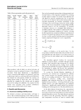
Table 2. Process parameters used in the present work The method accurately captures the evolving geometry and
thermal history of the deposited material. By activating
Elastic Specific Pressure Shear Shear Heat
modulus heat (N) translation rotation source specific regions in stages, the model closely simulates the
(GPa) (J/kg·K) (N) (N·m) (W/m ) real deposition process, guaranteeing that the growing
3
73.1 0.875 50 10 10 500 structure and its thermal and mechanical properties are
73.1 0.875 75 20 20 700 precisely represented. An essential component of this
technique is the model change interaction, which enables
73.1 0.875 100 30 30 800 the activation of new components corresponding to freshly
73.1 0.875 125 40 40 900 deposited material and the deactivation of elements
73.1 0.875 150 50 50 1,000 to represent removal or to disregard their influence at
73.1 0.875 175 60 60 1,100 specified moments. This method is implemented within
68.9 0.896 50 10 10 500 a coupled temperature–displacement analysis, allowing
68.9 0.896 75 20 20 700 for the simultaneous assessment of thermal and structural
68.9 0.896 100 30 30 800 behavior. The governing equations for this analysis include
the heat transfer equation and the structural momentum
68.9 0.896 125 40 40 900 balance, expressed in Equations 1 and 2, respectively:
68.9 0.896 150 50 50 1,000 T
71.7 0.96 50 10 10 500 c . . kT Q (I)
p
71.7 0.96 75 20 20 700 t
71.7 0.96 100 30 30 800
2
71.7 0.96 125 40 40 900 . f . u (II)
71.7 0.96 150 50 50 1,000 b t 2
71.7 0.96 175 60 60 1,100 where ρ is density, c is the specific heat, T is the
p
71 0.9 50 10 10 500 temperature, k is the thermal conductivity, Q is the internal
71 0.9 75 20 20 700 heat generation per unit volume, σ is the stress tensor, f is
b
71 0.9 100 30 30 800 the body force per unit volume, and is the displacement
71 0.9 125 40 40 900 vector.
71 0.9 50 10 10 500 The simulation approach involves the incremental
71 0.9 75 20 20 700 addition of material layers, controlled through element
71 0.9 100 30 30 800 activation. Each simulation step corresponds to a distinct
71 0.9 125 40 40 900 phase of the deposition process, during which specific
components are activated. This sequential deposition enables
the simulation to capture the thermal and mechanical
(dimensionless), both of which are critical indicators of changes, providing a realistic depiction of the AFSD process.
mechanical properties and performance of the deposited
structures. From these simulations, a comprehensive To account for thermal behavior, simulations of
dataset comprising 200 samples was generated, capturing convection and radiation are incorporated to estimate
a wide range of process conditions and material behaviors. heat transfer between the deposited material, the tool,
This dataset was subsequently divided into training and and the surrounding environment. These heat transfer
mechanisms influence cooling rates, temperature
testing subsets using an 80:20 split, with 160 samples gradients, and potential distortions in the build. The
allocated for training the ML models and 40 samples applied loading conditions – including frictional heating,
reserved for testing and validation. The coupled GA-ML applied pressure, and both longitudinal and rotational
models were evaluated using standard performance shear forces – significantly impact material flow, interlayer
metrics, such as RMSE, MAE, and R values. bonding, and the final geometry of the deposited structure.
2
3. Results and discussion In the finite element formulation, the computational
domain is discretized into smaller elements that can be
3.1. Numerical modeling of AFSD process
selectively activated and deactivated to precisely model the
The element activation and deactivation technique is material deposition process. The finite element equations
used in the numerical modeling of the AFSD process to are derived from the governing differential equations,
simulate the sequential addition and removal of material. and interpolation functions are used to estimate field
Volume 2 Issue 3 (2025) 36 doi: 10.36922/ijamd.5014