
Page 505 - IJB-10-1
P. 505
International Journal of Bioprinting Macro and micro structure of a 3D-printed implant
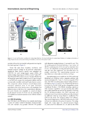
Figure 3. (a) Load and boundary conditions for wedge-shaped fixation; (b) stress distribution for wedge-shaped fixation; (c) topology optimization of
wedge-shaped structure; and (d) and loading and boundary conditions for bone plate fixation.
analysis software for tetrahedral mesh generation using the with diameters ranging between 15 μm and 45 μm). The
6
free mesh approach (Figure 2). 3D printing process involved utilizing a laser power of
200 W, a scanning rate of 0.6 m/s, and an exposure time
Under the same load, boundary conditions, and
material property settings in the previous optimization of 125 s. By selectively scanning and melting the powder
with the laser, the component was fabricated once the
simulation, three fixation models were simulated for powder crystallized. The manufacturing accuracy and
OWHTO: (i) solid wedge-shaped spacer (SWS), (ii) layer thickness in this study were both set at 30 μm.
optimal wedge-shaped spacer (OWS), and (iii) T plate (TP).
The SWS and OWS analyses aimed to validate whether the Upon printing process completion, the OWS underwent
WS topology optimization could achieve the same strength deburring and polishing using a magnetic polisher with
as the SWS and compare the mechanical stability with the stainless steel pins (Ø = 1 mm, L = 3 mm) at a speed of 2700
commercially available traditional T plate fixation system. rpm. The OWS was subsequently cleaned using ultrasonic
6
The comparison criteria included overall displacement, oscillations (Figure 5a and b). Our 3D printing laboratory
maximum equivalent stress in the plate, maximum is certified by the ISO 13485 quality management system
equivalent stress in the fixation screw, and maximum first (Certificate Number: 1760.190828), ensuring compliance
principal stress in the bone. For computational efficiency, with necessary regulations and guaranteeing that safety
the screw threads were simplified as cylindrical shapes and quality standards are met for the implants. Following
in all analyses because the focus was on comparing the the 3D printing procedure, the OWS underwent acid
HTO global mechanical responses under different fixation etching to remove any residual sandblast particles, followed
6
systems. by additional cleaning using ultrasonic oscillations. The
OWS in this study was designed using CAD software.
2.4. OWS 3D printing The detailed dimensions of all OWS features in the CAD
The OWS filled with YM lattices was manufactured using software were defined as the actual dimensions. The wedge
a metal 3D printer (AM250, Renishaw, Gloucestershire, height (H), wedge angle (A), anterior-posterior length
UK) with titanium alloy powder (Ti6Al4V ELI powder (L), and screw hole diameters (S1, S2, and S3) the OWS
Volume 10 Issue 1 (2024) 497 https://doi.org/10.36922/ijb.1584