
Page 508 - IJB-10-1
P. 508
International Journal of Bioprinting Macro and micro structure of a 3D-printed implant
excluding hairline cracks. The OWS system stability, commercial TP fixation method exhibited a distinct
compared to the commercial TP bone plate system, bone plate posterior movement trend and the proximal
was assessed when fixed onto the osteotomy tibia. This tibial plateau. As for the distribution of equivalent
evaluation was based on the maximum dynamic load stress within the implant, both SWS and OWS showed
capacity and the number of cycles that each group could concentration at the medial-posterior edge, while the
endure, providing valuable insights for mechanical analysis. TP bone plates were concentrated in the middle section
and screw concentrated on the contact regions between
3. Results cortical bone (Figure 7). It is worth emphasizing that the
The OWS manufacturing errors were both within 1% stress values for all three groups remained well below the
(maximum error of 0.96%), showing that the metal 3D fracture limit of approximately 1000 MPa.
printing equipment used in this study has good precision Table 5 recorded the medial-lateral displacement
and is suitable for medical applications (Table 3). difference, maximum load capacity, and corresponding
The FE analysis results indicated that there were cycle number for HTO under OWS and commercial TP
slight differences in the total displacement, maximum fixation conditions. The results showed that only one
first principal bone stress, and maximum equivalent sample experienced failure in the OWS fixation group, while
screw stress between the OWS and SWS modules, with two samples failed in the commercial TP fixation group
variations of 1.82%, 7.21%, and 2.18%, respectively. under failure condition 1 (medial-lateral displacement
However, the OWS exhibited a significant increase in difference > 2 mm). The OWS failure group exhibited a
69.39% in the maximum equivalent stress within the higher maximum load capacity [OWS: 4480N; TP: (4160
implant, reaching a value of 194.39 MPa when compared N + 3200 N)/2 = 3680 N] and a greater number of cycles
to SWS (Table 4). When comparing the stability between [OWS: 464038; TP: (458873 + 311636)/2 = 385254.5]. The
the OWS system and the commercial TP fixation method, fracture situations after dynamic fatigue testing for each
the OWS system exhibited significant reductions of group are shown in Figure 8. In the OWS fixation group,
56.46%, 11.98%, 64.31%, and 92.91% in terms of total only one sample displayed a minor visible collapse fracture
displacement, maximum equivalent implant stress, on the lateral cortical bone. In contrast, all three samples in
maximum first principal stress in the bone, and the commercial TP fixation group showed noticeable and
maximum equivalent stress on the screw, respectively. multiple crack-induced collapse fractures on the lateral
In terms of the total displacement distribution, the cortical bone. These results indicated that OWS fixation
Table 3. 3D printing error
Anterior-posterior length Screw hole
Wedge angle (A) Wedge height (H)
(L) S1 S2 S3
Actual dimension 12.000 12.000 40.000 8.000 5.500 5.500
Measurement 12.063 11.960 40.380 8.033 5.552 5.542
Error (%) 0.522 -0.333 0.950 0.417 0.939 0.758
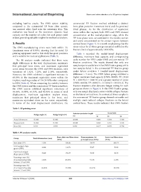
Table 4. FE analysis results
Bone plate von Mises stress Bone maximum 1st Screw von Mises stress
Group Total deformation (mm)
(MPa) principal stress (MPa) (MPa)
Bone plate (TP) 1.029 220.84 158.79 863.73
Solid wedged-shape 0.440 114.76 52.87 59.90
spacer (SWS)
Optimized wedged- 0.448 194.39 56.68 61.20
shape spacer (OWS)
Percentage error (%)
of corresponding value 1.82% 69.39% 7.21% 2.18%
between TP and SWS
Percentage error (%)
of corresponding value -56.46% -11.98% -64.31% -92.91%
between TP and OWS
Volume 10 Issue 1 (2024) 500 https://doi.org/10.36922/ijb.1584