
Page 507 - IJB-10-1
P. 507
International Journal of Bioprinting Macro and micro structure of a 3D-printed implant
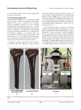
of our assembly bone plate should meet the requirements secured with a specific square clamp for the distal part and
for implant manufacture. a circular fixture for the proximal part on a material testing
machine (Instron E10000, Instron, Canton, MA, USA).
2.5. Biomechanical fatigue test Two medial and lateral extended plates attached onto the
The biomechanical fatigue test was conducted according proximal circular fixture were also prepared to measure the
to the literature to compare the mechanical performance corresponding displacement on both sides using miniature
using the OWS and the commercial HTO TP fixation linear potentiometers (Novotechnik T-0025, U.S. Inc.,
system by gradually increasing the load to simulate Germany) (Figure 6c).
complete weight-bearing during the gait cycle. 30,31 The test
samples were prepared using tibia sawbone material (Tibia, The experimental fatigue test involved a multi-stage
4th Gen., Composite, 17 PCF Solid Foam Core, Medium) cumulative loading procedure with increments of 160 N
to produce osteotomy models that were cut using a metal and was subjected to 20,000 cycles of dynamic loading at
saw machine to simulate a 12° corrective defect. The a frequency of 5 Hz at each stage. The loading started at
3D-printed OWS and the commercial TP system (A Plus 800 N and gradually increased up to 5440 N, completing
Biotechnology Co., Ltd., New Taipei City, Taiwan Region) 30 load stages or until the test samples failed. The medial
were subsequently fixed separately at the osteotomy site for and lateral linear potentiometer displacement values were
recorded during the experiment. Two failure criteria were
each group consisting of three sets (Figure 6a and b).
established: (i) a medial-lateral displacement difference on
Regarding the fatigue experimental setup, the distal the tibial plateau exceeding 2 mm, and (ii) the occurrence
and proximal tibia were embedded in epoxy resin and of a visible collapse fracture on the lateral cortical bone,
Figure 6. (a,b) Optimal wedge-shaped spacer (OWS) and T-shaped plate (TP) systems on sawbones; and (c) illustration of the biomechanical fatigue test
setup.
Volume 10 Issue 1 (2024) 499 https://doi.org/10.36922/ijb.1584