
Page 509 - IJB-10-1
P. 509
International Journal of Bioprinting Macro and micro structure of a 3D-printed implant
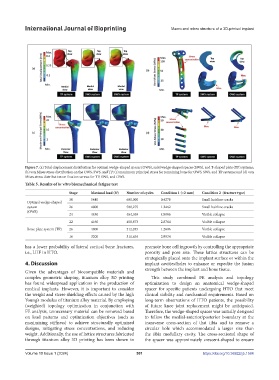
Figure 7. (a) Total displacement distribution for optimal wedge-shaped spacer (OWS), solid wedge-shaped spacer (SWS), and T-shaped plate (TP) systems;
(b) von Mises stress distribution on the OWS, SWS, and TP; (c) maximum principal stress for remaining bone for OWS, SWS, and TP systems; and (d) von
Mises stress distribution on fixation screws for TP, SWS, and OWS.
Table 5. Results of in vitro biomechanical fatigue test
Stage Maximal load (N) Number of cycles Condition 1 (<2 mm) Condition 2 (fracture type)
30 5440 600,000 0.4278 Small hairline cracks
Optimal wedge-shaped
system 26 4800 500,275 1.2462 Small hairline cracks
(OWS)
24 4480 464,038 4.9086 Visible collapse
22 4160 458,873 2.8764 Visible collapse
Bone plate system (TP) 26 4800 512,285 1.2606 Visible collapse
16 3200 311,636 2.9934 Visible collapse
has a lower probability of lateral cortical bone fractures, promote bone cell ingrowth by controlling the appropriate
i.e., LHF in HTO. porosity and pore size. These lattice structures can be
strategically placed onto the implant surface or within the
4. Discussion implant cavities/holes to enhance or expedite the fusion
Given the advantages of biocompatible materials and strength between the implant and bone tissue.
complex geometric shaping, titanium alloy 3D printing This study combined FE analysis and topology
has found widespread applications in the production of optimization to design an anatomical wedge-shaped
medical implants. However, it is important to consider spacer for specific patients undergoing HTO that meet
the weight and stress-shielding effects caused by the high clinical stability and mechanical requirements. Based on
Young’s modulus of titanium alloy material. By employing long-term observations of HTO patients, the possibility
(weighted) topology optimization in conjunction with of future knee joint replacement might be anticipated.
FE analysis, unnecessary material can be removed based Therefore, the wedge-shaped spacer was initially designed
on load patterns and optimization objectives (such as to follow the medial-anterior/posterior boundary at the
maximizing stiffness) to achieve structurally optimized transverse cross-section of that tibia and to remove a
designs, mitigating stress concentrations, and reducing circular hole which accommodated a larger size than
weight. Additionally, the use of lattice structures fabricated the tibia medullary cavity. The cross-sectional shape of
through titanium alloy 3D printing has been shown to the spacer was approximately crescent-shaped to ensure
Volume 10 Issue 1 (2024) 501 https://doi.org/10.36922/ijb.1584