
Page 72 - IJB-2-1
P. 72
Investigation of process parameters of electrohydrodynamic jetting for 3D printed PCL fibrous scaffolds with complex geometries
w/v, when the voltage is increased from 2 to 2.4 kV, where the fibre diameter doesn’t vary much and is sta-
the diameter increased from 55 to 95 μm. This is fol- ble. After a certain higher value of nozzle-to-substrate
lowed by the second region, where the effect of in- distance, the fibre diameter tends to decrease drasti-
creased voltage has less pronounced effect on the fibre cally. This is due to the reason that when the gap is
diameter. This may be due to the reason that in region larger, at the same supply voltage, the electric field
one, there lies the transition point at which the electric force at the nozzle tip reduces greatly and hence una-
field force reaches a critical value and when it exceeds ble to overcome the surface tension and viscoelastic
the combined effect of surface tension and viscoelastic forces and also the fibres were not very stable and
forces. However, at a higher solution concentration, the discontinuous. The trend is a bit different at very high
trend looks murky and no stable pattern and the effect solution concentration; in the plateau (middle) region
is also less pronounced, due to the dominant viscoelas- where for other lower concentrations (60% w/v, 70%
tic force. This may also be attributed to the complex w/v) the fibre diameter does not vary much, it de-
interaction between the supply voltage and nozzle-to- creases in the higher concentration solution (80% w/v),
substrate distance, which goes hand in hand. again due to the dominant viscoelastic force.
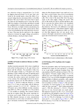
Figure 7. Effect of supply voltage on fibre diameter. Figure 8. Effect of nozzle-to-substrate distance on fibre diameter.
3.4 Effect of Nozzle-to-substrate Distance on Fibre 3.5 3D Printing of PCL Scaffolds with Complex
Diameter Geometries
Another important parameter which plays a significant From the parametric study, the E-jetting process was
role in the E-jetting process is the gap between the optimized and range for each parameter is obtained
nozzle and the substrate. This parameter works rela- so as to get stable, continuous E-jetting fibres. The
tive to the supply voltage, i.e., if the gap is very small, concentration of the PCL solution was fixed at 70% w/v,
applying a higher voltage will result in sparking and if stage speed at 150 mm/s, supply voltage 2.5 to 3 kV,
the gap is very large, a very high voltage is required to solution feed rate 4−10μL/min and nozzle -to-substrate
overcome the surface tension and viscoelastic forces distance 2.5 or 3 mm for all the subsequent experimental
of the solution. The relationship between the nozzle- trials. Scaffolds of different geometries, with complex
to-substrate distance and the fibre diameter is shown architecture were printed. Semi-lunar or curved scaf-
in Figure 8. Nozzle-to-substrate distance is varied folds are printed as shown in Figure 9. This geometry
from 1.5 to 3.5 mm, in small steps, with all other pa- is necessary for reconstruction of soft tissues espe-
rameters constant (V = 2.5 kV, Fd = 10μL/min, S = cially the knee meniscus [35] . The E-jetting parameters
150 mm/s) and at three different solution concentra- were C = 70%, Fd = 8uL/min, V = 3 kV, S = 150 mm/s
tions (60% w/v, 70% w/v and 80% w/v). Values below and D = 2.5 mm. Several trials were made and the
1.5 mm resulted in sparking. The observed relation- fibre diameter measured was 90 ± 5 µm. A novel spir-
ship has no regular trend. But certain important ob- al scaffold was also printed as shown in Figure 10 for
servations can be made. While at lower values of gap, the first time. The E-jetting parameters were, for Fig-
the fibre diameter increases at some concentrations ure 10C, C = 70%, Fd = 6 uL/min, V = 2.5 kV, S = 100
and decreases at some other concentrations when the mm/s and D = 3 mm, and for Figure 10D, C = 70%,
gap is increased, eventually there is a plateau region, Fd = 0.4 uL/min, V = 2.55 kV, S = 100 mm/s and
68 International Journal of Bioprinting (2016)–Volume 2, Issue 1