
Page 89 - IJB-2-1
P. 89
Wen Shing Leong, Shu Cheng Wu, Kee Woei Ng, et al.
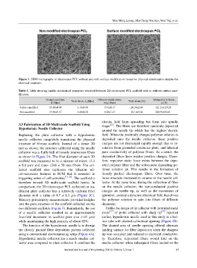
Figure 1. SEM micrographs of electrospun PCL without and with surface modification reveal no physical deterioration despite the
chemical treatment.
Table 1. Table showing similar mechanical properties observed between 2D electrospun PCL scaffold with or without surface mod-
ification
Young’s modulus, Yield stress, σ y [Mpa] Ultimate tensile stress, Yield strain [%] Elongation at break,
E [Mpa] σ UTS [Mpa] ε f [%]
Surface modified 15.86±4.00 3.14±0.48 5.91±0.17 20.34±2.98 321.13±118.25
Non modified 13.96±5.35 2.48±0.28 6.28±1.47 19.14±5.06 260.79±58.65
electric field from spreading but form into spindle
3.3 Fabrication of 3D Multi-scale Scaffold Using shape [37] . The fibers are therefore randomly deposited
Hypodermic Needle Collector around the needle tip which has the highest electric
Replacing the plate collector with a hypodermic field. When the positively charged polymer solution is
needle collector completely transforms the physical deposited onto the needle collector, these positive
structure of fibrous scaffold. Instead of a dense 2D charges are not discharged rapidly enough due to in-
mat as shown, the structure collected using the needle sulation from grounded conductor plate, and inherent
collector was a fluffy ball of loosely interwoven fibers poor conductivity of polymer fibers. As a result, the
as shown in Figure 2A. The fiber diameter of such 3D deposited fibers have residue positive charges. There-
scaffold was measured to be a mixture of micro- (3.3 fore, repulsive static force exists between the depo-
± 0.6 µm) and nano- (240 ± 50 nm) fibers. The col- sited polymer fiber and the subsequent depositing po-
lected scaffold also replicates the inherent mi- lymer solution jet. This results in the formation of
cro-nanoscale features in ECM that is essential in loosely packed electrospun fibers. Over time, the
triggering series of cell activities [31–36] . The scaffold is loose structure increased in volume on the needle col-
therefore termed 3D multi-scale scaffold herein. In lector. At the same time, during the collection of fiber
comparison, the 2D electrospun PCL collected on tra- on the needle collector, the non-conducted positive
ditional plate collector has a relatively uniform fiber charges on needle tip, as well as the movement of
diameter with a value of 0.7 ± 0.3 µm (Figure 2C). spinneret, created a dynamic electrical field that drives
Mercury porosimetry measurements provided insights the polymer solution to spin into fibers of different
into the pore structure of the scaffold collected on the diameters.
two different scaffolds (Figure 3). Remarkably, the use Unlike the design of tip collector with protruded metal
of a needle collector resulted in an approximately struts [37] or point collector with sharp tip [38] reported
four-fold increment in scaffold pore size (~42 µm) earlier, hypodermic needle used in this study is a hol-
while maintaining the high porosity of about 92%. low tube with slanted cylindrical opening (Figure 4B).
The function of the hypodermic needle is to disrupt The slanted area of needle opening offered alternate
the closely packed fiber deposition pattern collected landing surface for fiber deposition when the sharpest
using a conventional electrospinning setup (Figure 4A). tip was occupied and reduced in electrical conductivi-
Hypodermic needle collector has a much smaller col- ty. Therefore, deposited fibers would fold on the
lector area compared to plate collector. It confines the needle collector when subsequent fibers landed on the
International Journal of Bioprinting (2016)–Volume 2, Issue 1 85