
Page 91 - IJB-2-1
P. 91
Wen Shing Leong, Shu Cheng Wu, Kee Woei Ng, et al.
examined to study the effect of pore size of electros-
pun scaffold on cellular distribution in scaffold after
cell seeding. Both types of scaffolds were surface
modified with the chosen surface modification method
demonstrated in Section 3.1, and compared to that
without surface modification. As discussed earlier,
surface modification significantly enhanced hydrophi-
licity of the PCL scaffold without deteriorating the
architectural properties. As shown in Figure 5, 3D
Figure 3. Mercury porosimeter revealed a four-fold increment
in pore size in 3D scaffold in comparison with 2D scaffold, multi-scale electrospun PCL improved in water ab-
with little change in porosity. sorption and expanded in phosphate buffer solution
only after effective surface modification.
slanted needle opening instead of the needle tip. Cell culture results as shown in Figure 6 revealed
Eventually, newly spun fibers would wrap around the the difficulty for HDFs to be seeded into traditional
needle tip and develop into a cotton-like scaffold. The
scaffold thickness collected within 30 minutes was 2D electrospun scaffold. Traditional 2D PCL elec-
more than 6 mm and this is about 75 times more than trospun scaffold had desired porosity for tissue engi-
that in 2D electrospun PCL scaffold. On the other neering but the dense fiber packing resulted in small
hand, existence of a mixture of micro- and nano- fiber pore size which restricted cell to be seeded throughout
could play a part in disrupting fibers packing, result- the whole scaffold (Figure 6A). Even with the aid of
ing in an increase of the pore size of the scaffold [19–22] . gelatin grafting to improve wettability and cell-sca-
Larger pore size offers higher opportunities for cell ffold interaction, no significant improvement in cellu-
infiltration and mass transfer without sacrificing the lar distribution was observed. HDFs seeded on gelatin
ECM mimicry nanofeatures. grafted 2D electrospun scaffold were found to adhere
on the top surface only, despite the enhanced wettabil-
3.4 Comparison of HDFs Distribution Between 2D ity (Figure 6B). This is a common issue that has re-
Electrospun and 3D Multi-scale Scaffold [9,10]
stricted the application of electrospun scaffold . By
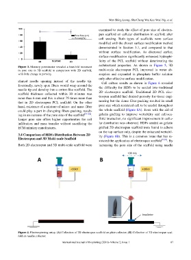
Both 2D electrospun and 3D multi-scale scaffold were increasing the pore size of the scaffold using needle
100 m/s
Figure 4. Electrospinning setup. (A) Collection of 2D electrospun scaffold on plate collector; (B) Collection of 3D electrospun scaf-
fold on needle collector.
International Journal of Bioprinting (2016)–Volume 2, Issue 1 87