
Page 91 - IJB-2-2
P. 91
Weiguang Wang, Guilherme Ferreira Caetano, Wei-Hung Chiang, et al.
temperature [29,30] . Its relevant properties are indicated following process parameters: melting temperature
o
in Table 1. (90 C); slice thickness (220 μm); screw rotation veloc-
ity (22 rpm) and deposition velocity (20 mm/s). PCL
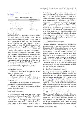
Table 1. Material properties of PCL
and PCL/pristine graphene scaffolds containing diff-
Density 1.146 g/mL at 25°C erent concentrations of graphene (0.25% wt, 0.50% wt
o
Melting point 58–60 C and 0.75% wt) were produced using a screw-assisted
o
Glass transition temperature ≈ –60 C additive manufacturing system from RegenHU (3DD-
Molecular weight (Mw) 50000 g/mol iscovery, Switzerland). In this process, the material is
Specific heat of vaporisation 1 kJ/g molten in the liquefier tank, pressed to the barrier
3
Solubility parameter (δ) –9.43 (cal/cm ) screw tank by compressed air, and extruded out thr-
ough a 330 μm nozzle. PCL/pristine graphene pellets
Pristine Graphene were initially prepared by melt blending. Produced
Pristine graphene was prepared via water-assisted liq- scaffolds presented well dispersed pristine graphene,
uid phase exfoliation of graphite. Briefly, 50 mg as previously reported using Raman spectroscopy and
[4]
microcrystalline graphite powder (325 mesh, 99.995% micro Raman mapping .
pure, purchased from Alfa Aesar) was immersed in 2.3 Thermogravimetric Analysis
N-methyl-2-pyrrolidone (NMP) mixture with a 0.2
mass fraction of water. The initial concentration of The onset of thermal degradation and pristine gra-
−1
graphite was fixed at 5 mg mL for exfoliation. NMP, phene content in the scaffolds was assessed using a TA
99% extra pure, was purchased from ACROS OR- Instruments Q500 TGA equipped with an evolved gas
GANICS. The materials were batch sonicated for 6 analysis furnace. Thermogravimetric analysis (TGA)
was performed on neat PCL scaffolds as controls, and
hours in a bath sonicator (Elma sonic P60H, Switzer- pristine graphene loaded PCL scaffolds. Scans were
land) at a fixed nominal power and frequency of 100 performed in an air atmosphere (flow at 60 mL/min)
W and 37 kHz, respectively. Sample dispersions were with a temperature range from room temperature to
hanged on for overnight in between sonication and 560°C at a rate of 10°C/min. Measurements were
centrifugation, and were centrifuged at 3000 rpm for taken using sample mass of 6 ± 1 mg in platinum pans.
30 minutes using a Hettich, EBA20. The upper 75% The weight losses of the PCL/pristine graphene com-
of the colloidal supernatant were collected and dried posite structures were monitored and used to calculate
in an oven to yield the graphene nano-sheets. the final pristine graphene contents.
Melt-Blending Process 2.4 Morphological Characterisation
PCL/pristine graphene blends were prepared accord- Scanning electron microscopy (SEM) was used to
ing to the following steps: investigate the morphology of produced scaffolds and
PCL pellets were melted up to 70ºC; to measure pore size (PS) and filament width (FW),
Pristine graphene flakes were added to the polymer by comparing obtained values with the initial design
melt at desired concentrations (0.25% wt, 0.50% wt parameters (Figure 1). SEM was conducted with a
and 0.75% wt); Quanta 200 SEM system, using an accelerating volt-
The blend was physically mixed for 15 minutes to age of 10 kV. All relevant dimensions were measured
ensure good pristine graphene dispersion; using the software Image J. The average and standard
After mixing, the blended material was cool down deviation obtained from 6 measurements are reported
and cut into small pellets. for each scaffold.
2.2 Scaffold Fabrication 2.5 Apparent Water-in-air Contact Angle
A three-dimensional block model was initially desig- The contact angle indicates the wettability of the ma-
ned in a computer-aided design (CAD) software (Sol- terial surface, being an important parameter in order to
o
o
idWorks, Dassault Systems). A 0 /90 lay-down pat- understand the biological interaction between the
tern was adopted to obtain pores with a regular square scaffolds and cells. The balance of forces regarding
geometry while maintaining a constant filament dis- the surface tension between liquid-vapour (γ ) for a
lv
tance of 680 μm. Scaffolds were produced using the liquid drop and the interfacial tension between the solid
International Journal of Bioprinting (2016)–Volume 2, Issue 2 97