Page 554 - IJB-10-2
P. 554

International Journal of Bioprinting                              OLS design for distal femur osseointegration


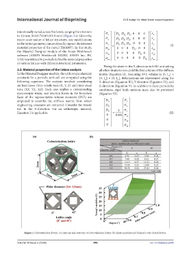
            intentionally varied across five levels, ranging from 0.6 mm   σ      D  D  D  0  0  0  ε  
            to 1.0 mm (0.6/0.7/0.8/0.9/1.0 mm) (Figure 1a). Given the     x      11  12  13     x  
                                                                                               ε
            micro-scale nature of lattice structures, any modifications    σ y    DD D 23  0  0 0  0    y  
                                                                              22
                                                                           21
            to the lattice geometry can profoundly impact the inherent    σ   z    =   DD D 33  0  0  0   ε z     (I)
                                                                              32
                                                                           31
            material properties of the metal (Ti6Al4V). In this study,    σ xy     00  0  D 44  0  0    ε  
                                                                                               xy
            the Material Designer module of the Ansys Workbench    σ      00  0  0  D  0    ε  
            software (ANSYS Workbench 2022R2, ANSYS Inc., PA,       yz               55      yz  
            USA) was utilized to precisely define the material properties    σ   zx       00  0  0  0 D  ε   
                                                                                            66   zx
            of various lattices with different structural parameters.
                                                                  Fixing the strain in the X-direction to 0.001 and setting
            2.2. Material properties of the lattice analysis   all other strains to zero yield the first column of the stiffness
            In the Material Designer module, the orthotropic elasticity   matrix (Equation II). Assuming RVE volume as [0, L ] ×
                                                                                                          x
            constants for a periodic unit cell are computed using the   [0, L ] × [0, L ], deformations are represented along the
                                                                           z
                                                                   y
            following  equations.  The  analysis  involved  considering   X-direction (Equation III), Y-direction (Equation IV), and
            six load cases: three tensile tests (X, Y, Z) and three shear   Z-direction (Equation V). In addition to these periodicity
            tests (XY, YZ, XZ). Each case applies a corresponding   conditions, rigid body motions must also be prevented
            macroscopic strain, and reaction forces in the boundary   (Equation VI).
            faces of the representative volume elements (RVE) are
            employed to assemble the stiffness matrix, from which    D      σ  
                                                                                x
                                                                    11
                                                                              
            engineering constants are extracted. Consider the tensile     D 21     σ y 
            test in the X-direction. For an orthotropic material,    D   1  σ    
            Equation I is applicable:                               31  =     z                        (II)
                                                                              
                                                                          .
                                                                    0    0 001 σ xy 
                                                                    0        σ  
                                                                              yz 
                                                                     0     σ   zx  


                Figure 1. Cuboctahedron lattice. (a) Unit size and structure of cuboctahedron lattice; (b) elastic modulus and Poisson’s ratio of each lattice.


            Volume 10 Issue 2 (2024)                       546                                doi: 10.36922/ijb.2590
   549   550   551   552   553   554   555   556   557   558   559