
Page 78 - IJB-3-1
P. 78
Influence of electrohydrodynamic jetting parameters on the morphology of PCL scaffolds
folds with controlled micron scale patterns were fa- stage was controlled using Ensemble IDE software
bricated. PCL solution prepared by dissolving PCL running on a desktop PC and connected through a
pellets in acetic acid was used to fabricate 3D scaf- serial USB port, gave the real-time position and ve-
folds. This study mainly investigated the influence of locity information for monitoring and compensation
the stage speed on fibre characteristics and scaffold purposes.
pattern. Morphology of the EHD-jetted PCL fibres
and scaffolds were analysed using optical microscope 2.2 Material Preparation
images and scanning electron microscope (SEM) im- PCL is a type of biodegradable polyester normally
ages. Multi-layer scaffolds with varied coiled pattern used for fabrication of scaffolds. A solution of PCL is
were fabricated and analysed. Cell attachment and obtained by dissolving the PCL pellets in acetic acid.
proliferation have to be investigated in the future by PCL pellets with an average molecular weight of
further cell culture studies on these multi-layer coiled 90 kDa, were purchased from Scientific Polymer
scaffolds. Products Inc., USA. Acetic acid with 99.7% purity
2. Methodology was purchased from Aladdin Industrial Corporation,
USA. Material preparation involves dissolving the
2.1 EHD-jetting System Design and Setup PCL pellets in acetic acid, and sonicating it in an ul-
trasonic bath at 6 0 °C until it turns into a colourless
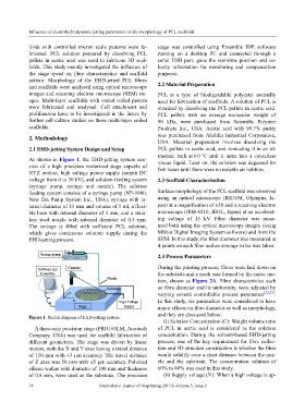
As shown in Figure 1, the EHD-jetting system con- viscus liquid. Later on, the solution was degassed for
sists of a high precision motorized stage capable of few hours until there were no notable air bubbles.
XYZ motion, high voltage power supply (output DC
voltage from 0 to 30 kV), and solution feeding system 2.3 Scaffold Characterization
(syringe pump, syringe and nozzle). The solution
feeding system consists of a syringe pump (NE-1000, Surface morphology of the PCL scaffold was observed
New Era Pump System Inc., USA), syringe with in- using an optical microscope (BX51M, Olympus, Ja-
ternal diameter of 13 mm and volume of 5 ml, a flexi- pan) at a magnification of ×50 and a scanning electron
ble hose with internal diameter of 3 mm, and a stain- microscope (JSM-6510, JEOL, Japan) at an accelerat-
less steel nozzle with internal diameter of 0.5 mm. ing voltage of 15 kV. Fibre diameter was meas-
The syringe is filled with sufficient PCL solution, ured both using the optical microscopy images (using
which gives continuous solution supply during the MShot Digital Imaging System software) and from the
EHD-jetting process. SEM. In this study, the fiber diameter was measured at
4 points on each fiber and an average value was taken.
2.4 Process Parameters
During the printing process, fibres were laid down on
the substrate and a mesh was formed by the raster mo-
tion, shown as Figure 2A. Fibre characteristics such
as fibre diameter and its uniformity, were adjusted by
varying several controllable process parameters [22,23] .
In this study, six parameters were considered to have
major effects on fibre diameter as well as morphology,
and they are discussed below:
Figure 1. Sketch diagram of EHD-jetting system.
(i) Solution Concentration (C): Weight volume ratio
A three-axis precision stage (PRO165LM, Aerotech of PCL in acetic acid is considered as the solution
Company, USA) was used for scaffold fabrication of concentration. During the solvent-based EHD-jetting
different geometries. The stage was driven by linear process, one of the key requirement for fibre collec-
motors, with the X and Y axes having a travel distance tion and 3D structure construction is whether the fibre
of 150 mm with ±3 μm accuracy. The travel distance would solidify over a short distance between the noz-
of Z axes was 50 mm with ±5 μm accuracy. Polished zle and the substrate. The concentration solution of
silicon wafers with diameter of 100 mm and thickness 60% to 80% was used in this study.
of 0.8 mm, were used as the substrate. The precision (ii) Supply voltage (V): When a high voltage is ap-
74 International Journal of Bioprinting (2017)–Volume 3, Issue 1