
Page 391 - IJB-10-3
P. 391
International Journal of Bioprinting Optimizing 3D-printed mouthguards
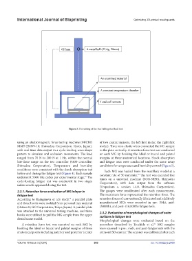
Figure 3. The setting of the free-falling steel ball test.
using an electromagnetic force testing machine (MICRO of two central incisors, the left first molar, the right first
MMT-250NV-10; Shimadzu Corporation, Kyoto, Japan), molar). Three non-elastic wires connected the MG sample
with real-time data output in a cycle-loading wave-shape to the plate vertically. A retention force test was conducted
pattern to simulate oral occlusion movements. The load on each MG by hooking the labial or buccal and palatal
ranged from 70 N to 200 N at 1 Hz, within the normal margins at three anatomical locations. Shock absorption
bite-force range on the test controller (4830 controller; and fatigue tests were conducted under the same setup
Shimadzu Corporation). Temperature and humidity conditions for temperature and humidity control (Figure 5).
conditions were consistent with the shock absorption test Each MG was hauled from the maxillary model at a
before and during the fatigue test (Figure 4). Each sample constant rate of 50 mm/min. The test was executed five
30
underwent 5000 bite cycles per experimental stage. The times on a universal machine (SCG-5KNA, Shimadzu
29
cycle-loading fatigue test was conducted in two stages Corporation), with data output from the software
unless cracks appeared during the test. (Trapezium x, version 1.4.0, Shimadzu Corporation).
2.3.1. Retention force evaluation of MG inlayer in The gauges were recalibrated after each measurement.
fatigue test The maximum force represented the retention force. The
According to Karaganeva et al.’s study, a parallel plate retention forces of conventionally fabricated and additively
30
and three hooks were molded from personal tray material manufactured MGs were recorded in pre- (0th), mid-
(Ostron II, GC Corporation, Tokyo, Japan). A parallel plate (5000th), and post- (10,000th) fatigue tests.
was attached to the universal testing machine, and three 2.3.2. Evaluation of morphological changes of outer
hooks were utilized to pull the MG sample from the upper surfaces in fatigue test
dental stone model.
Morphological changes were evaluated based on the
A retention force test was executed on each MG by procedure described by Tsuchida et al. MG samples
31
hooking the labial or buccal and palatal margins of three were scanned in pre-, mid-, and post-fatigue tests with the
anatomical points including anterior and posterior (center extraoral 3D scanner. The scanner was calibrated after each
Volume 10 Issue 3 (2024) 383 doi: 10.36922/ijb.2469