
Page 529 - IJB-10-3
P. 529
International Journal of Bioprinting Mechanical responses of 3D-printed AFO
Table 1. Comparison between traditional methods and 3D a baseline AFO design is created and 3D printed. An FE
printing for ankle-foot orthosis (AFO) production model is developed and validated using experimental
data. A parametric study on the effect of base materials,
Parameter Traditional 3D printing
techniques techniques thickness, and trimline location is conducted. The results
Material options Limited Most engineering provide insights into the development and customization
thermoplastics of 3D-printed AFOs for individuals with specific ankle and
Labor requirement Skilled Technical foot conditions.
Material waste High Low 2. Methods
Design Low High
repeatability 2.1. Surface modeling of the foot and leg
Design freedom Moderate High The 3D surface model of the foot and leg was acquired
for the virtual design of the AFO. A progressive
Accuracy Low High
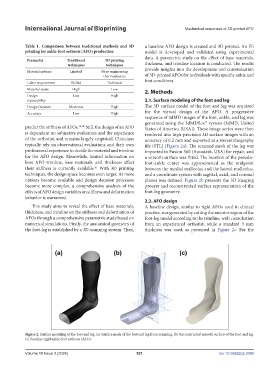
sequence of 3dMD images of the foot, ankle, and leg was
generated using the 3dMDflex™ system (3dMD, United
predict the stiffness of AFOs. 34-40 Still, the design of an AFO States of America [USA]). These image series were then
is dependent on subjective evaluation and the experience rendered into high-precision 3D surface images with an
of the orthotist, and remains largely empirical. Clinicians accuracy of 0.2 mm and exported as a stereolithography
typically rely on observational evaluations and their own file (STL) (Figure 2a). The scanned mesh of the leg was
professional experience to decide the material and trimline imported to Fusion 360 (Autodesk, USA) for repair, and
for the AFO design. Meanwhile, limited information on a smooth surface was fitted. The location of the pseudo-
how AFO trimline, base materials, and thickness affect foot-ankle center was approximated as the midpoint
their stiffness is currently available. With 3D printing between the medial malleolus and the lateral malleolus,
41
techniques, the design space becomes even larger. As more and a coordinate system with sagittal, axial, and coronal
options become available and design decision processes planes was defined. Figure 2b presents the 3D imaging
become more complex, a comprehensive analysis of the process and reconstructed surface representation of the
effects of AFO design variables on stiffness and deformation foot-leg geometry.
behavior is warranted.
2.2. AFO design
This study aims to reveal the effect of base materials, A baseline design, similar to rigid AFOs used in clinical
thickness, and trimline on the stiffness and deformation of practice, was generated by cutting the anterior region of the
AFOs through a comprehensive parametric study based on foot-leg model according to the trimline, with consultation
numerical simulations. Firstly, the anatomical geometry of from an experienced orthotist, while a standard 3 mm
the foot-leg is established by a 3D-scanning system. Then, thickness was used, as presented in Figure 2c. For the
Figure 2. Surface modeling of the foot and leg. (a) Surface mesh of the foot and leg from scanning. (b) Reconstructed smooth surface of the foot and leg.
(c) Baseline rigid ankle-foot orthosis (AFO).
Volume 10 Issue 3 (2024) 521 doi: 10.36922/ijb.3390