
Page 531 - IJB-10-3
P. 531
International Journal of Bioprinting Mechanical responses of 3D-printed AFO
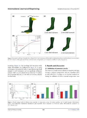
Figure 3. Numerical modeling of the ankle-foot orthosis (AFO). (a) Finite element (FE) model to simulate plantarflexion and dorsiflexion motions of AFO.
(b) AFO moment–ankle angle relationships of different mesh configurations. (c) Comparisons of different mesh configurations.
modeling (Figure 3c). The resulting AFO moment–ankle 3. Results and discussion
angle relationships are displayed in Figure 3b. A good
convergence was achieved with a 2-mm element size shell 3.1. Validation of numerical results
element (11,659 elements), and no significant difference The numerical results were validated by experimental data
between shell and solid elements was observed. To reduce through a uniaxial compression test on a baseline AFO
the computational cost, a 2-mm shell element was selected printed with PA12. As there is no standard method for
for this study. testing the stiffness of AFOs, uniaxial compression was
Figure 4. Tensile testing results of different base materials: (a) stress–strain curves, (b) elastic modulus, and (c) yield strength. Abbreviations:
PCTG: Polycyclohexylene dimethylene terephthalate glycol-modified; PA12: Polyamide 12; PA12-CF: Carbon fiber-reinforced polyamide 12;
PLA: Polylactic acid.
Volume 10 Issue 3 (2024) 523 doi: 10.36922/ijb.3390