
Page 530 - IJB-10-3
P. 530
International Journal of Bioprinting Mechanical responses of 3D-printed AFO
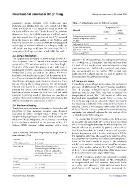
parametric design, different AFO thicknesses, base Table 3. Printing temperature for different materials
materials, and trimline locations were considered in this Temperature (°C)
study. The baseline AFO design was used to study the Material
Build
thickness and base materials. The thickness of the AFO was Nozzle platform
determined from the shell thickness, and trimline location
was determined from the portion of the AFO trimmed Polycyclohexylene dimethylene 265 90
terephthalate glycol-modified
from the pseudo-foot-ankle center to the posterior and (PCTG)
inferior directions. The location of the trimline was adjusted Polyamide 12 (PA12) 270 100
accordingly to produce different AFO designs, while the
calf height was kept at 45 mm for consistency. Table 2 Carbon fiber-reinforced 285 90
polyamide 12 (PA12-CF)
summarizes the design variables considered in this work.
Polylactic acid (PLA) 220 45
2.3. Sample fabrication
The samples were fabricated via FDM using a Creality K1 capacity of 30 kN was utilized. The testing was performed
Max 3D printer. The CAD model of the samples was first at a loading rate of 1 mm/min. The reaction force from
converted to STL and sliced with a 0.1 mm layer height. the load cell and displacement were measured by a long
Each slice of the model has two perimeter walls and an travel extensometer. Additionally, a uniaxial compression
infill density of 100%. Then, the toolpath information was test was conducted on the baseline AFO printed with
written into G-code and sent to the printer. A 0.4-mm PA12 material. A digital camera was used to capture the
hardened steel nozzle was utilized, and the standard 1.75- deformation of the AFO during testing.
mm filament was used for all materials. All filaments were
dried before printing to avoid moisture absorption from 2.5. Numerical model
the air. During the printing process, the thermoplastic FE modeling was employed to investigate the mechanical
filament was heated to a semiliquid state and extruded responses of AFOs under PF- and DF-loading conditions.
through the nozzle onto the heated build platform to The FE package ABAQUS/Implicit 2020 (Dassault
facilitate adhesion between the first layer and the build Systèmes Simulia Corp, USA) was used to develop the
platform. A printing speed of 100 mm/s was used for all computational model. The CAD model of AFOs was
samples. The nozzle and build platform temperatures for imported into HyperMesh (Altair, USA) to create the
different materials are summarized in Table 3. FE mesh and exported to ABAQUS. Figure 3a presents
the boundary conditions of the computational model. A
2.4. Mechanical testing coupling constraint was assigned between the calf section
Tensile tests were conducted to characterize the mechanical of the AFO and a reference point, while a second coupling
properties of base materials. Samples were designed constraint was assigned between the foot section of the
according to ASTM standard D638. Three Type IV AFO and another reference point.
42
samples with gauge length of 33 mm, width of 6 mm, and
thickness of 4 mm were printed for each material according To simulate the PF and DF motions, the bottom part
to the conditions described in the previous section. An of the AFO was fixed, and a 10° rotation about the virtual
Instron 5900R universal testing machine with a load ankle center was applied through the reference points. The
contact behavior was modeled by general contact with a
hard formulation for the normal direction and a penalty
Table 2. Variables considered for parametric design of ankle- friction formulation with a friction coefficient of 0.3 for
foot orthoses (AFOs) the tangential direction. The constitutive behavior of the
43
Variable Conditions base material was simplified to be elastic perfectly plastic
AFO thickness (mm) 2; 3; 4; 5; 6 based on the tensile results in Figure 4. The rotational
displacement and reaction moment of the calf section were
Base material Polycyclohexylene dimethylene extracted for further evaluation. The PF and DF stiffnesses
terephthalate glycol-modified (PCTG);
polyamide 12 (PA12); carbon fiber- of the AFO were calculated as the slope of the linear region
reinforced polyamide 12 (PA12-CF); in the AFO moment–ankle angle relationship.
polylactic acid (PLA) A mesh convergence analysis was conducted to evaluate
Trimline/trim depth the mesh density required based on the optimization
(mm) of computational cost and accuracy. Four-node linear
Posterior 10; 15; 20; 25 tetrahedral solid element (C3D4) and four-node linear
Inferior 10; 15; 20; 25 quadrilateral shell element (S4) were considered for
Volume 10 Issue 3 (2024) 522 doi: 10.36922/ijb.3390