
Page 99 - IJB-4-1
P. 99
Pre-clinical evaluation of advanced nerve guide conduits using a novel 3D in vitro testing model
supported the culturing of primary and non-primary seeding procedures by directly applying the cell
neuronal and Schwann cells by following standard cell suspension on the nerve guide scaffold without the
culture protocols in a more complex, multilayered need of a pump perfusion system for the supply of
environment represented by the conduit scaffold medium. As shown in Figures 3B and 3C, neuronal
architecture under investigation cell orientation on the internal fibre scaffold was
compared to cells on TCP. In monolayer, cells are
3.1 Design of the In Vitro Testing Setup and randomly arranged and evenly attached to the TCP
Example Device substrate (Figure 3B).
The developed 3D model used a PEG nerve guide
conduit filled with PCL microfibres, based on the
procedures developed by Pateman et al., [17] and Daud
et al. [18] . Figure 1A shows a detailed schematic of the
production of PEG conduits with an internal PCL
microfibre scaffold. PEG conduits, fabricated by
microstereolithography, measured 5 mm in length and
had an internal diameter of 1.2 mm with a wall
thickness of 250 µm (Figure 1B). The internal lumen
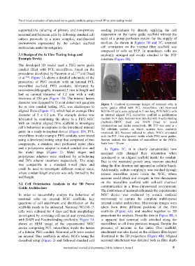
diameter was designed to fit a rat dorsal root ganglion Figure 3. Confocal microscopy images of neuronal cells in
for ex vivo conduit testing. PCL was electrospun to nerve guides filled with PCL microfibres. (A) Neuronal
aligned fibres (Figure 1C), which had an average fibre NG108–15 cells were cultured in 5 mm long PEG NGCs with
diameter of 5 ± 0.2 µm. The example device was an internal aligned PCL microfibre scaffold in proliferation
fabricated by combining the above to a PEG NGC medium for 4 days. Neurons were labelled with F-actin-binding
with an internal aligned fibre scaffold to investigate phalloidin-TRITC (red) and DAPI (blue) to reveal
cell’s behaviour in response to the introduced internal cytoskeletons and nuclei respectively. (B) TCP was used as a
flat substrate control, on which neurons were randomly
guide in a ready-to-implant device (Figure 1D). PCL orientated. (C) Neurons cultured in whole NGCs orientated
microfibres inside example PEG conduits were tested with the PCL fibre alignment inside whole PEG nerve guides.
using a developed testing setup that comprised of two Arrows indicate the direction of microfibres in the NGCs.
components, a stainless steel perforated metal plate Scale bars = 20 µm.
and a polystyrene adapter to match conduit size and In Figure 3C, it is clearly demonstrated how
the metal stage (Figure 2). Metal stages and neuronal cells changed their orientation when
polystyrene adapters were sterilised by autoclaving introduced to an aligned scaffold inside the conduit.
and 70% ethanol treatment respectively. The setup Due to the restricted growth area, neurons attached
was compatible to a standard 6-well plate and along the fibre direction and appeared as cellular bands.
could be used to investigate different conduit sizes, Additionally, culture complexity was reached through
where conduit length analysis was only limited by the several microfibre layers inside the NGC, where
well height. neurons could attach and elongate in two dimensions
3.2 Cell Orientation Analysis in the 3D Nerve on the microfibre scaffold with cell-cell chemical
Guide Architecture communication in a three-dimensional environment.
The distribution of neuronal cells inside the experimental
In order to successfully analyse the behaviour of NGC device was evaluated by z-stack confocal
neuronal cells on internal NGC scaffolds, key microscopy to capture the complete multilayered
questions of cell attachment and distribution on the internal conduit architecture. Microscope images were
scaffolds needs to be answered. Neuronal NG108-15 taken from three different positions of the fibre
cells were cultured for 4 days and their morphology scaffolds (Figure 4A) and stacked together to 3D
investigated by revealing cell nuclei and cytoskeleton projections for analysis. From the data in Figure 4B, it
with DAPI and F-actin-binding phalloidin. Figure 3A is apparent that neuronal cells attached along the
shows an SEM image of the experimental NGC microfibres on all three positions imaged. Despite the
device comprising PCL microfibres inside the lumen presence of neurons in the entire fibre scaffold,
of a tubular PEG conduit. Neuronal cells were seeded attachment was also found on the different fibre layers
on internal fibre scaffolds in whole NGCs using the illustrated in the 3D projections (Figure 4B). Aligned
described setup (Figure 2) and followed standard cell neuronal attachment was detected both in fibre depth
International Journal of Bioprinting (2018)–Volume 4, Issue 1 5