
Page 99 - IJB-4-2
P. 99
Han X, et al.
process relies on a photo-polymerisation process and coated tubes were prepared by dipping a mandrel with a
®
suitable resins consist of monomers and photo-initiators diameter of 1.1 mm in the BLI with Irgacure 184 resin
(PI) that are typically toxic. Consequently, for biomedical and cured manually six times for a minute under an
applications, it is paramount to guarantee that the PI argon-filled beaker by turning the mandrel gently. After
degrades completely during the polymerisation process. the sample was exposed to 50% ethanol for 5 minutes,
This challenge can only be overcome by interdisciplinary tubes are pull up from the mandrel, dried in vacuum and
process improvement, including material, SLA-process irradiated for another 5 minutes under an inert condition
and environmental conditions since in state-of-the-art with UV light. SLA fabricated tubes were prepared as
implementations a typical degree of polymerisation is discussed in the previous section. Two groups of dip
between 40–70% resulting in a considerable amount coated samples, and two groups of SLA fabricated tubes
of remaining PI [47] . A promising approach to guarantee were treated at 36 °C in each case in PBS buffer or 3%
complete polymerisation and to prevent the formation H2O2 for two months. The difference in weight of all
of unwanted compounds uses inert atmosphere. Only in samples was determined and analysed.
the absence of oxygen, it is possible to achieve complete 3.4 In vitro testing of the vascular network
crosslinking and full disappearance of cytotoxic PI
and monomers. The SLA process was developed in
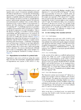
this work to produce the vascular network. Figure 9 3.4.1 3.4.1. Cell Culture
illustrates the setup of the SLA process. It consists of a 3 Human adipose-derived stem cells (hASCs) and
illustrates CryLaS GmbH, Germany), a scanner system pericytes were isolated from human tissue derived
(ProSeries PS1 Scan Heads - Cambridge Technology) from patients that underwent regular surgical treatment
with an F-theta lens (f=100mm) for fast beam deflection and signed an informed content at the BG University
in x-y-direction. The polymer bath was positioned on a Hospital Bergmannsheil in Bochum, Germany. The
platform connected to a piezo-axis to allow positioning hASCs were cultured in DMEM-HAMS-F12, and the
in the z-direction. For process development, different pericytes were cultured in a pericytes-growth-medium
photo resins in combination with a photo-initiator 355 (PGM, PromoCell).
nm were investigated. Detailed SLA setting is shown in
Figure 10. 3.4.2 3.4.2. Cell Seeding
3.3 Degradation test method of a printed tube In the context of the study as a scaffold methacrylated
gelatin (5%; IGB) was used . Using methacrylated
[5]
Degradation tests were carried out using dip coated gelatin and a photoinitiator (LAP; INN) a stable
tubes and SLA fabricated tubes. Quantification method hydrogel was created. Within this hydrogel, three diverse
of degradation was similar to ISO 10993-13. Dip species of cells were spread: 600,000 HUVECS, 600,000
hASCs and 60,000 pericytes. In the hydrogel three
different shapes of tubes were created: 1) a stainless steel
moulded tube, 2) a single tube printed using BLI with
®
Irgacure 184 and 3) a branched network printed using
®
BLI with Irgacure 184.
3.4.3 3.4.3. The bioreactor system
[27]
The bioreactor system was developed in driven by a
pump-sleeve-system to deliver medium (620 μL/min)
to the hydrogels. The pump was connected to a nutrient
bottle and the hydrogel containing chamber (see Figure
11). To run the bioreactor system a medium mixture was
performed in the same ratio as the corresponding cells
were distributed. The hydrogels were at least cultured
and 37°C and 5% CO for seven days.
2
3.4.4 3.4.4. Cell staining
After seven days a live/dead assay was performed
staining the hASCs with Calcein (green) and
Propidiumiodid (red).
Figure 10. SLA process setups.
International Journal of Bioprinting (2018)–Volume 4, Issue 2 9