
Page 198 - IJB-10-4
P. 198
International Journal of Bioprinting Horsetail-inspired lattice for bone use
The operation ensures that the joints will not be PL 3
closed to avoid flow obstruction as shown in Figure 1C. δ = 3 E I (I)
Figure 1C also illustrates that for a strut in the lattice that is beam
taken as the strut of interest, it is cut by lattice planes (010), where δ is the deflection; P and L represent the point
(001), and (100). The three cutting planes imply that the force applied and the length of the beam, respectively; E beam
flange counts must be in multiples of three. represents the elastic modulus of the beam material; and
I represents the moment of inertia of the cross-section
Our study focused on the convoluted effects of varying
(1) outer radius, r, and (2) wall thickness, t, on the effects of the beam. By simplifying the struts of lattice as hollow
cylinders, I can be represented by the following equation:
of mechanical performance. The r is varied from 0.70 mm
to 1.75 mm with 0.15 mm increment. The range of r was Π r ( 4 − r 4 )
selected, in consideration of maintaining sufficient fidelity I ( hollowcylinder) = outer 16 inner (II)
of the inter-flange separation distances at smaller outer t t
r
r
radius sizes, and preservation of full strut feature at larger where r outer =+ , and r inner =− . Intuitively,
2
2
outer radius sizes. The t of the lattice is varied from 0.15 I would increase with increasing r, consequently reducing
mm to 0.40 mm with arbitrary increments. The samples δ for the same magnitude of external force (or strain
are named in the naming nomenclature of xxxryyyt, where applied). Kolken et al. reported that non-restrained flaps
xxx represents r in 10 mm and yyy represents t in 10 -2 may be utilized for increasing surface areas of lattice sub-
-2
mm. The range of thickness was selected, in consideration structure without altering mechanical properties. Thus,
29
of maintaining sufficient material with smaller thickness for the hollow struts with flanges in the current study, the
and keeping the nominal φ at lower than 40% at bigger effect of non-connected flanges would not be studied as it
thickness. We limited φ to not significantly exceed 40% to is expected that there would not be appreciable mechanical
provide sufficient porosity as well as allow a lightweight difference between hollow struts and struts with connected
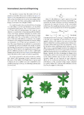
design to mimic that of the bone. Figure 2 shows the general flanges. Similarly, the effect eliminating the flanges while
view of the lattices when t and r are varied, respectively.
retaining the central connection point was not evaluated
The design proposed in our study consists of a hollow as the central portions may be seen as thin strut BCC
BCC lattice with supporting flanges connected toward elements, which are not expected to have substantial
the center of the hollow strut. Beam theory may be used effects on the mechanical performance. The mechanical
to discuss the use of hollow strut. For a standard fix-free performance of the connected flange design compared
cantilever loading of a beam, the following equation may to a purely hollow BCC had not been evaluated and was
be considered. therefore investigated in this study.
Figure 2. Variations of outer radius and wall thickness.
Volume 10 Issue 4 (2024) 190 doi: 10.36922/ijb.2326