
Page 199 - IJB-10-4
P. 199
International Journal of Bioprinting Horsetail-inspired lattice for bone use
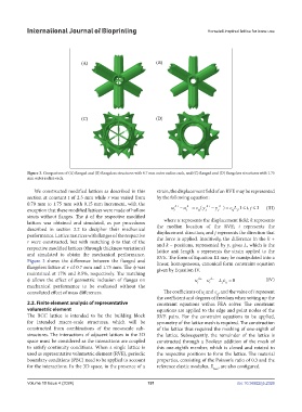
Figure 3. Comparison of (A) flanged and (B) flangeless structures with 0.7 mm outer radius each, and (C) flanged and (D) flangeless structures with 1.75
mm outer radius each.
We constructed modified lattices as described in this strain, the displacement field of an RVE may be represented
section at constant t of 2.5 mm while r was varied from by the following equation:
0.70 mm to 1.75 mm with 0.15 mm increment, with the k+ k− k+ k−
exception that these modified lattices were made of hollow u i − u i = ε ij y ( j − y j ) = ε ij L ,1 ≤ i j ≤, 3 (III)
j
struts without flanges. The φ of the respective modified
lattices was obtained and simulated, as per procedures where u represents the displacement field; k represents
described in section 2.2 to decipher their mechanical the median location of the RVE; i represents the
performance. Lattice matrices with flanges of the respective displacement direction; and j represents the direction that
the force is applied. Intuitively, the difference in the k +
r were constructed, but with matching φ to that of the
respective modified lattices (through thickness variations) and k – positions, represented by y, gives L, which is the
lattice unit length. ε represents the strain applied to the
and simulated to obtain the mechanical performance. RVE. The form of Equation III may be manipulated into a
Figure 3 shows the difference between the flanged and linear, homogeneous, canonical form constraint equation
flangeless lattice at r of 0.7 mm and 1.75 mm. The φ was given by Equation IV.
maintained at 17% and 8.5%, respectively. The matching
φ allows the effect of geometric inclusion of flanges on u i k+ − u i k− − L ε = 0 (IV)
jij
mechanical performance to be evaluated without the
convoluted effect of mass differences. The coefficients of u and ε , and the value of i represent
ij
i
the coefficient and degrees of freedom when setting up the
2.2. Finite element analysis of representative constraint equations within FEA solver. The constraint
volumetric element equations are applied to the edge and point nodes of the
The BCC lattice is intended to be the building block RVE pairs. For the constraint equations to be applied,
for intended macro-scale structures, which will be symmetry of the lattice mesh is required. The construction
constructed from combinations of the mesoscale sub- of the lattice thus required the meshing of one-eighth of
structures. The interactions of adjacent lattices in the 3D the lattice. Subsequently, the remainder of the lattice is
space must be considered as the interactions are coupled constructed through a Boolean addition of the mesh of
to satisfy continuity conditions. When a single lattice is this one-eighth member, which is cloned and rotated to
used as representative volumetric element (RVE), periodic the respective positions to form the lattice. The material
boundary conditions (PBC) need to be applied to account properties, consisting of the Poisson’s ratio of 0.3 and the
for the interactions. In the 3D space, in the presence of a reference elastic modulus, E , are also configured.
base
Volume 10 Issue 4 (2024) 191 doi: 10.36922/ijb.2326