
Page 261 - IJB-10-4
P. 261
International Journal of Bioprinting Cell viability in printing structured inks
equivalent material viscosity, equivalent average shear coaxial printing for constructing soft and hard tissues such
stress is determined to validate the reasonableness of the as blood vessels and bones. For symmetric inks, the
49
48
equivalent material. maximum wall shear stress in the material phase loaded
τ ave = 1 969. µ + 0 003021. (V) with cells was regarded as the equivalent target. Since
the phase interface is directly connected to the wall, the
maximum shear stress at the interface is also found on the
where τ and µ represent the average shear stress and wall. For core–shell inks, the maximum wall shear stress
ave
dynamic viscosity, respectively.
and interface shear stress in the material phase loaded with
The relationship between viscosity and shear stress cells were considered as equivalent targets. The average
of homogeneous inks is a prerequisite for subsequent shear stress of the equivalent materials was then validated.
equivalent analysis; it serves as the link between viscosity For symmetric inks with different ink combinations,
analysis and validation of average shear stress. Note that, Figure S18 (Supplementary File) presents the qualitative
for convenience, only materials falling within the density
and viscosity range of structured inks were selected for results of shear stress, with quantified data shown in Figure
equivalent analysis. When the material viscosity obtained 11A and C. Figure 11A illustrates the maximum shear
from the equivalent analysis falls outside this range to stress on the walls corresponding to the fluid domains
some extent, it is speculated that Equations VI and V of phases 1 and 2. The ink combinations were denoted
still hold true. This is attributed to the constant velocity as “a-b,” where “a” represented the viscosity of ink 1, and
gradient, which is maintained by the constant velocity at “b” represented the viscosity of ink 2, as shown in Figure
the outlet, ensuring a constant material volume flow rate. S2 (Supplementary File). Taking the ink combination
When the inlet velocity changes, these two equations need of 3.23–3.394 as an example, the maximum wall shear
to be adjusted, but viscosity and shear stress may remain stress corresponding to phase 1 was 1.661e+2 Pa, and for
positively correlated. phase 2, it was 1.891e+2 Pa. As the viscosity of inks in the
combination increased, the wall shear stress corresponding
3.6. Equivalent cases using symmetric and to the fluid domains of both phases 1 and 2 increased. In
core–shell inks different ink combinations, the maximum shear stress
Symmetric inks were considered because this ink structure on the wall corresponding to the fluid domain of phase 2
has been reported for bioprinting multicomponent consistently exceeded that on the wall corresponding to
structures. These structured inks are easily prepared using the fluid domain of phase 1. Cells may be present in two
23
mold-assisted method, given the simple cross-section distinct flow domains, corresponding to phases 1 and 2,
of both material phases. Core–shell inks were chosen respectively. Given the different cell distributions in the
for investigation due to their widespread application in two flow domains, corresponding equivalent homogeneous
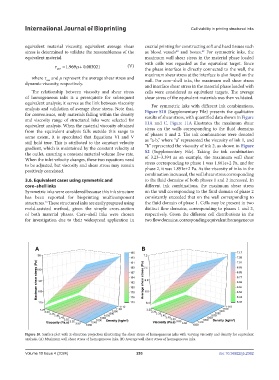
Figure 10. Surface plot with Z-direction projection illustrating the shear stress of homogeneous inks with varying viscosity and density for equivalent
analysis. (A) Maximum wall shear stress of homogeneous inks. (B) Average wall shear stress of homogeneous inks.
Volume 10 Issue 4 (2024) 253 doi: 10.36922/ijb.2362