
Page 380 - IJB-10-4
P. 380
International Journal of Bioprinting 3D cartilage induction and monitoring
chamber (Figure 1B) and the input and output cylinders With Reynolds number (Re) = 4.6, the channel length (L)
(IO cylinders, Figure 1C). The geometry of the cell required to fulfill previous conditions was 22.7 mm, while
chamber consisted of a middle ring of 24 mm to storage the pipe length of IO cylinders was 35 mm, which was
the IPFP-MSC-loaded 3D scaffold and a total length of 45 higher than necessary, for the flow to reach the scaffold
mm, where only 5 mm corresponded to scaffold size. Rest chamber (Video S1, Supporting Information). The near
distances (20 mm per side) were introduced to prevent the (natural focus in these transducers) field length (N) was:
near-field effect of the ultrasound signal.
The IO cylinders were PMMA rods with 30 mm Df (XIII)
2
diameter and 40 mm length, and they were perforated N = c 4
from the cell contact face to create fluid channels (Figure
S1, Supporting Information). The viable length of the IO where c was the longitudinal speed of sound of PMMA,
cylinders enables fully developed laminar flow within f the main frequency, and D the diameter of the transducer.
them. When fluid enters a pipe, the minimum length to be Based on the defined parameters (e.g., c = 2730 m·s ), N
−1
fully developed must fulfill the following: was calculated to be 15.4 mm.
For transducer coupling, a simple system, comprising
L 1
= 44. Re 6 (XII) a hollow cylinder with a restriction ring, was designed
D to retain the transducer and a bTPUe pillow that exerted
enough pressure to acquire a precise signal (Figure 1D).
The fluid applied in this research was culture medium, Figure 1E schematically represents the electronic BR
which was Newtonian (ρ = 1009 kg·m ; µ = 0.63 mPa·s). assembly. The wave generator (Rigol Inc., USA) was
49
−3
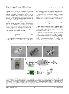
Figure 1. Bioreactor (BR) design. (A) Rendered image of the final BR design (with cell chamber and transducers coupled). (B) Rendered image of the BR
cell chamber and the input and output (IO) cylinders. (C) Rendered image of the IO channels. (D) Visual concept of the transducer with the coupling
system. (E) Electronic closed-circuit BR assembly: (a) Olympus preamplifier connected to the (b) recording oscilloscope and (c) transducer (receiver);
(d) cell chamber and core of the BR; (e) transducer (transmitter) directly connected to the (f) wave generator; (g) Raspberry Pi receives signals from the
oscilloscope and controls the Arduino board; (h) Arduino Uno regulates pump rotation speed and flow rate; (i) peristaltic pump exerts laminar fluid flow
through the BR; and (j) medium reservoir with a 0.22-µm filter for O and CO exchange.
2 2
Volume 10 Issue 4 (2024) 372 doi: 10.36922/ijb.3389