
Page 383 - IJB-10-4
P. 383
International Journal of Bioprinting 3D cartilage induction and monitoring
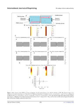
Figure 3. Finite element model (FEM) of P-wave propagation. (A) 2D representation of the different domains of FEM. (B) Thermal image of the
displacement at specific directions (i.e., X direction) in the ultrasound transducer (transmitter), at (a) t = 0.5 µs and (b) t = 1 µs. (C) P-wave propagation
at different times: (a) t = 0.5 µs, (b) t = 1 µs, (c) t = 15 µs, (d) t = 18 µs, (e) t = 34 µs, and (f) t = 50 µs. (D) Thermal image of the displacement in specific
directions (i.e., X direction) in the ultrasound transducer (receiver) at (a) t = 35 µs and (b) t = 40 µs. (E) The final modeled electrical signal obtained from
FEM. Abbreviation: PMMA, polymethyl methacrylate.
Volume 10 Issue 4 (2024) 375 doi: 10.36922/ijb.3389