
Page 474 - IJB-10-4
P. 474
International Journal of Bioprinting 3D-bioprinted peripheral nerve scaffold
NGF release at 51.88 ± 2.12 pg/ml (Figure 7D). This used, and no nanomaterials were introduced. Although the
result indicated that scSHEDs had elevated levels of NGF freeze-drying had its limitations, it was sufficient to display
release compared to SHEDs. Taken together, most SHEDs the porous microstructure of this hydrogel. It has been
underwent differentiation to form scSHEDs. reported that porous structures can enhance cell growth
43
and vascularization, suggesting that our hydrogel provided
3.2. Physical and chemical characteristics of an optimal environment for promoting cell adhesion,
the bioinks proliferation, and ultimately nerve fiber regeneration.
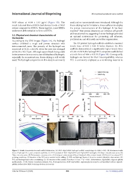
According to the SEM images (Figure 3A), the hydrogel
surface exhibited a rough and porous structure with The 3D-printed hydrogel scaffolds exhibited a maximal
interconnected pores. The porosity of the hydrogel was tensile force of 0.02 ± 0.01 N before fracture; the PCL
measured at 58.32 ± 24.33%, while the pore size averaged scaffolds demonstrated a significantly higher tensile force
at 166.58 ± 102.72 μm. Although supercritical drying could of 4.00 ± 0.34 N; the hydrogel-PCL composite scaffolds had
better preserve the microstructure of dehydrated hydrogels, a tensile force of 4.06 ± 0.32 N (Figure 3B). Consequently,
especially the nanostructures, freeze-drying is still widely hydrogels are favored for their biocompatibility, whereas
used. The hydrogel composition in this study is commonly PCL is commonly employed as a reinforcing material to
Figure 3. Bioink characterization and scaffold fabrication. (A) RGD-Alg/GelMA hydrogel scaffold morphology via SEM (×320). (B) Maximum tensile
force of hydrogel, PCL, and composite scaffolds. (C) FTIR analysis of RGD-Alg/GelMA and Alg/GelMA hydrogels. (D) Shear–viscosity rate curve. (E)
Time–viscosity curve. (F) Temperature–viscosity curve. (G) Computer-aided design of the printed path of the conduit model. (H) Nozzle 1 to evaluate PCL
printing conditions. (I) Structure of the PCL nerve conduit before rolling. (J) PCL and hydrogel layers of the nerve conduit (dried for observation). (K)
PCL and hydrogel layers after crosslinking. (L) 3D structure of the conduit. Scale bar: 0.5 mm. ***p < 0.001. Abbreviations: Alg/GelMA: Alginate-gelatin
methacrylate; FTIR: Fourier transform infrared; PCL: Polycaprolactone; RGD-Alg/GelMA: arginine-glycine-aspartic acid-modified sodium alginate-
gelatin methacrylate; SEM: Scanning electron microscopy.
Volume 10 Issue 4 (2024) 466 doi: 10.36922/ijb.2908