
Page 122 - IJB-5-1
P. 122
Liu F, et al.
dissolved in Dulbecco’s phosphate-buffered saline voltage of 10 kV; frequency of 50 kHz). The plasma is
(DPBS) (Sigma-Aldrich, UK), and then mixed with MA generated from the top central electrode, expanding to the
(Sigma-Aldrich, UK) at 23% v/v of alginate solution surrounding air inside and outside the nozzle.
under vigorous stirring. The pH of the solution was kept The control system consists of a motion control
around 7.4 during the reaction time by the addition of 5M system, temperature control system, and gas supply
NaOH. The reaction time was 24 h. After the chemical control system. The motion control system utilizes
modification, the polymer solution was precipitated with a Geo Brick LV motion controller (Delta Tau Data
cold ethanol, dried in an oven overnight at 45°C and Systems, Inc) to manipulate all motors. The built-in
purified through dialysis for 6 days. The solution was software allows for complete machine logic control,
then frozen at −80°C and recovered by lyophilization. including G code execution. The temperature control
Gelatin was functionalized by dissolving gelatin bovine system consists of four digital temperature controllers
skin type B (Sigma-Aldrich, UK) at a concentration of (P.I.D. Omron E5CN), which is used to precisely control
12.5%, in DPBS (Sigma-Aldrich, UK) at a temperature of the temperature in the extruder heating chamber with
45°C. After gelatin dissolution, MA (×10 molar excess) polyimide thermos-foil heating elements (Omega Online/
was added under vigorous. The pH of the solution was Kapton Heaters) and thermocouples (Omega). The gas
kept around 7.0–8.0 during the reaction. The reaction supply control system includes an air compressor which
time was 6 h. The solution was purified through dialysis works as the main gas supply, regulators, and gauges
for 7 days, frozen at −80°C and the polymer recovered by (SMC, UK), which enables pressure on/off control and
lyophilization. manual adjustment. Power supply (230V ac, PHOENIX
CONTACT) offers 24v output voltage and 40A current
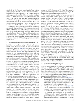
2.3. Plasma-assisted Bio-extrusion System Set Up for all the control system. Safety considerations were
Scaffolds were produces using a hybrid AM system taken into account regarding the electrical parts, including
called PABS, being developed at the University of fuses, main circuit breakers, main filter, push buttons and
Manchester. PABS (Figure 2A) comprises two main estops (all supplied by OneCall Electronics Company,
units, a multi-extrusion unit and a three-inlet plasma UK), and circuits. The control software was developed
modification unit (Figure 2B). The multi-extrusion unit in MATLAB as previously reported and G code files
consists of two pressure-assisted extruders and one were generated containing all the instructions for the
[30]
screw-assisted extruder, allowing operating a range of fabrication process .
biomaterials, such as synthetic biopolymers, hydrogels, This configuration enables multi-material dispensing
and biopolymer/ceramic composites. The extrusion unit and plasma modification in a sequential mode. The
has four movements: One rotational movement (C1) for system is able to achieve a maximum linear velocity of
selecting the required extrusion heads, a second rotational 20 mm/s and a resolution of 0.05 mm.
movement (C2) for driving and controlling the screw 2.4. Scaffolds Printing Strategies
rotational speed of the screw-assisted extruder, and two
linear movements (X and Y) in the X-Y plane. All these Scaffolds with a cross-section of 10 mm × 10 mm and a height
four movements are controlled by stepper motors and of 3 mm were fabricated using the single laydown pattern of
CNC drives. The build platform moves in the Z-direction 0/90° and a filament distance of 1 mm with a pore size of
and constitutes the sixth controllable axis. The build 1 mm (slice thickness of 0.5 mm; heating temperature of 90°C;
platform was fabricated using 7076 aluminum plate extrusion screw rotational speed of 15 rpm; and nozzle tip size
(250 mm × 200 mm × 7.5 mm) and is attached to the of 0.5 mm.). The strategies for printing hybrid scaffolds and
Z-axis rail guide with L-shape support underneath. plasma treated scaffolds are as follows (Figure 3):
The plasma modification unit is mounted on the X-Y • Hybrid PCL/hydrogel scaffolds fabrication (Figure 3A):
platform which is coplanar with the extrusion platform. After the scaffold being printed with a screw-assisted
Both platforms share common cylindrical guide rails in extruder, the extruder selection unit rotated with 120°,
the X-direction. The Y-direction movement (V axis) for and then the hydrogel solution was printed in the
the plasma modification unit is independently driven by pores using the pressure-assisted extruder.
a stepper motor parallel to the Y-axis of the extrusion • Full-layer treated scaffolds fabrication (Figure 3B):
unit. A quartz capillary (outside diameter of 7 mm; inner The N plasma modification was performed after
2
diameter r of 5 mm; and length of 70 mm) with three one layer PCL was deposited, and the process was
gas inlets serves as the reaction jet. A tungsten rod (inner repeated until the last layer of PCL was complete.
diameter of 2 mm) and one copper film (10 mm of width) The treatment was conducted at a pressure of
wrapped around the quartz tube serve as the high-voltage 0.689 bar and a flow rate of 5 L/mm. The deposition
and ground electrodes, respectively. The electrode is speed of the plasma jet was 3 mm/s, and each layer
connected to a high-voltage DC power supply (applied was subjected to the plasma treatment for 1 min. The
International Journal of Bioprinting (2019)–Volume 5, Issue 1 3