
Page 57 - IJB-5-1
P. 57
Gao D, et al.
in this area and gives readers a basic introduction to tension force, and weight of the spherical cap. The force
some important theories related to EHD inkjet printing. balance is given in equation (1):
The following section specially discusses liquid cone F+Δpπr =2πrγcosθ+W (1)
2
formation, the cone-jet transition, and jet stability. In this two plate experimental geometry, the value of
the force, F, exerted on a cylinder of length, L, is :
[17]
3.1 Formation of the Liquid Cone Shape VL 1
22
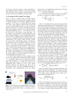
Figure 1A shows a common setup for EHD printing. F = 4 H 2 2 L 3 (2)
The pressure head of the liquid in the cylindrical nozzle ln R − 2
is initially adjusted by the pressure regulator until the
meniscus “A” in Figure 1A is almost flat at the nozzle
exit. Then, a high voltage is applied between the metal Above, F is the attractive force due to the imposed field;
nozzle and a grounded electrode to create an electrical ΔP is the pressure difference between inside the liquid cone
potential difference. The electric field strength near the at its base and ambient pressure; γ is the surface tension;
apex of an operating jet can be close to the threshold for R is the nozzle radius; L is the distance between the end of
electrical breakdown of air (3 × 10 V/m), but a cone- nozzle and plate E; W is the hydrodynamic force including
6
the weight of liquid in the spherical cap above the orifice;
jet only forms in the absence of gas discharge . As and θ is the semi-cone angle. The hydrodynamic force ΔP
[31]
the voltage is increased, the increasing Maxwell stress continuously supplies fluid to the emerging droplet .
[33]
causes liquid deformation, from a hemispherical droplet In the classical theory of dielectrics, the charge is
in Figure 1B to a roughly conical meniscus in Figure 1C. situated at the interface between two substances, which
The process of surface deformation is triggered by small have different dielectric constants . Thus, electro forces,
[36]
perturbations of the surface, which, in turn, enhance which stem from two isotropic media which have different
the local electric field through charge concentration, electrical conductivity and dielectric constant within or
and further increase the electrostatic pull in a cascading across the phase boundaries , induces electrical charges
[37]
effect . The conical meniscus is maintained over a which exist in the fluid along the fluid interface .
[32]
[38]
certain critical limit of electric potential , and a limiting While surface tension tends to keep the pendant droplet
[33]
case is reached when the apex of the cone approaches a in spherical shape which has the smallest surface-to-
point, i.e., a singularity . Inside the conducting nozzle, volume ratio, and also to reduce interfacial energy , the
[32]
[39]
the liquid is electrically neutral before emerging from
the nozzle outlet, and there is no charge separation in repulsion between the surface charges acts against the
[38]
the nozzle regardless of liquid conductivity because the surface tension force to deform the sphere into cone .
If pressure (ΔP) at the top of the fluid equal to zero,
electric field inside the nozzle is zero. the cone semi-vertical angle (θ) is 49.3°. If the weight
In 1964, Taylor obtained the first analytical model
for the cone structure and constructed a modal analysis of the fluid is also neglected, the critical voltage (static
equilibrium would no longer be maintained) for the
of a conducting liquid cone at equilibrium (without appearance of cone with a straight generatrix before
[40]
a jet from the apex) [32,35] . In 1969, Taylor used the two the jet forms can be predicted by equation (3) which is
plate experimental setup to explore the criteria for the derived by substituting equation (2) into equation (1) :
[17]
deformation from a sphere to a cone. At the critical
potential difference, the spherical cap above the tip V = 2 H (ln 2 L − )( 2πγ 493.) (3)
3
o
r cos
of the tube is taken to be in an equilibrium defined by L R 2
electrostatic force, hydrodynamic force, the surface Above the critical voltage, the static equilibrium value
would no longer be maintained . For a liquid meniscus
[17]
formed at the exit of a conducting needle, like electrodes
A B
of the needle to plate setup, the critical voltage can be
approximately calculated as [41,42] :
2γ R cos θ 4 l
V ≈ ln (4)
C critical ε 0 R
Where l is the distance between the electrode of nozzle
and electrode of substrate. This expression is valid when
Figure 1. (A) A schematic of electrohydrodynamic printing setup. the electrode separation l is much larger than the radius
[5]
Ethylene glycol liquid meniscus (B) at 0 volts; (C) at 2.5kV . of nozzle r . This formula only gives an approximation
[34]
Adapted by permission from Lozano et al. (2004) under the to the required starting voltage (experimentally verified
Elsevier license.
International Journal of Bioprinting (2019)–Volume 5, Issue 1 3