
Page 45 - IJB-5-2
P. 45
Feng F, et al.
A B C
D E
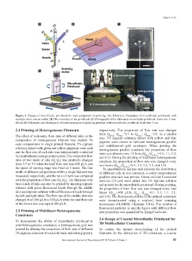
Figure 1. Design of microfluidic printhead for multicomponent bioprinting. (A) Schematic illustration of microfluidic printheads with
multiple inlets and an outlet. (B) The assembly of the printhead. (C) Photograph of the fabricated microfluidic printhead. Scale bar=5 mm.
(D and E) Schematic and photograph of multicomponent bioprinting platform with microfluidic printhead. Scale bar=5 cm.
2.4 Printing of Heterogeneous Filaments respectively. The proportion of flow rate was changes
from Q : Q =0:1 to Q : Q =1:0. In a similar
The effect of volumetric flow ratio of different inks on the way, 3% alginate solutions mixed with yellow and blue
black
white
black
white
composition of heterogeneous filament was studied. To pigment were chosen to fabricate heterogeneous parallel
code compositions in single printed filament, 3% alginate and multilayered grid constructs. When printing the
solutions mixed with green and yellow pigments were used heterogeneous parallel construct, the proportion of flow
and the flow rate of each inlet was independently controlled rates was altered every 10 lines (Q :Q =2:1, 1:1, 1:2,
by a multichannel syringe pump system. The volumetric flow and 0:1). During the printing of multilayer heterogeneous
blue
yellow
ratio of two kinds of inks (Q :Q ) was gradually changed construct, the proportion of flow rate was changed every
2
1
from 3:7 to 7:3 when the total flow rate was 600 µL/h and two layers (Q :Q =0:1, 1:3, 1:1, 3:1, and 1:0).
the speed of moving stage was fixed at 5 mm/s. The line To quantitatively analyze and simulate the distribution
yellow
blue
width of different compositions within a single filament was of different cells in one construct, a coded compositional
measured, respectively, and the ratio of them was compared gradient structure was printed. Green and red fluorescent
with the proportion of flow rate (Q :Q ). The filaments with particles (10 μm) were added into 3% alginate solution
2
1
three kinds of inks can also be printed by injecting alginate and printed by the microfluidic printhead. During printing,
solution with green fluorescent beads through the middle the proportion of their flow rate was changed every four
inlet and alginate solution with red fluorescent beads through layers (Q =600 µL/h, Q : Q =0:1, 1:2, 1:1, 2:1,
total
red
green
the left and right inlets. The flow rate of the middle inlet was and 1:0). The fluorescent profiles of the printed constructs
changed from 200 µL/h to 120 µL/h when the total flow rate were reconstructed using a confocal laser scanning
of the three inlets was kept at 600 µL/h. microscope (OLS4000, Olympus, USA). The number of
fluorescent particles in specific layers with different flow
2.5 Printing of Multilayer Heterogeneous rate proportion was quantified by ImageJ software.
Constructs
To demonstrate the ability of microfluidic printhead to 2.6 Design of Coaxial Microfluidic Printhead for
3D Multicellular Constructs
print heterogeneous constructs, a heterogeneous grid was
printed by altering the proportion of flow rate of different To realize the instant cross-linking of the printed
3% alginate solutions mixed with black and white pigment, filaments for the fabrication of 3D constructs, a coaxial
International Journal of Bioprinting (2019)–Volume 5, Issue 2 41