
Page 47 - IJB-5-2
P. 47
Feng F, et al.
by injecting 3% alginate solution (high viscosity) and A C
1% alginate solution (low viscosity) into the microfluidic
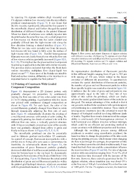
printhead simultaneously (Figure 3). It was found that
the ink viscosity significantly affected the flow pattern in B D
the microfluidic channel and further changed the spatial
distribution of different bioinks in the printed filament.
When two kinds of solutions were initially injected into
the printhead at the same flow rate, only a small proportion
of low-viscous ink flowed into the outlet channel and
gradually diffused into the high-viscous side along the
flow direction forming a slanted interface (Figure 3C).
When the two inks were extruded out from the nozzle,
low-viscous ink was found to fully cover the surface of
high-viscous inks (Figure 3D). Parallel heterogeneous Figure 3. Flow pattern and printed filaments of alginate solution
filaments were not clearly formed even when the flow rate with different viscosities. (A) Injecting 3% alginate solution (high
of low-viscous solution gradually increased (Figure S2A, viscosity) simultaneously and (B) printed heterogeneous filaments.
B, C, D). This implied that the presented multicomponent (C) Injecting 3% alginate solution and 1% alginate solution and
(D) printed filaments. Scale bars are 200 µm and 1 mm.
bioprinting is applicable to the inks with similar viscosity.
The previous studies indicated that when the fluids have
various viscosities, multiphase flow (liquid-liquid two the representative distribution of fluorescent particles
phase) occurs [26-31] . Since most of the bioinks are miscible within different heights ranging from 65 µm to 585 µm
fluid and surface tension, diffusivity at the interface is an with spacing of 130 µm, which related to the layers
important factor to regulate the flow pattern . consisted of different ink proportion. To quantitatively
[32]
3.2 Printing of Constructs With Graded evaluate the spatial distribution of fluorescent particles,
the number of green and red fluorescent particles within
Component Composition these specific heights was counted as shown in Figure 5H.
Figure 4A demonstrated a 2D filament pattern with It indicates that the ratio of green and red particles was
gradually changed ink proportion by continuously approximately equal to the ratio of flow rate of two
varying the flow rate ratio of two color-coded inks from kinds of inks within the printhead, which can finally
2:1 to 0:1 during printing. A grid pattern with five layers achieve the spatial gradient distribution of the particles as
was printed with continuous changed composition as designed. The unique advantage of this method is that it
shown in Figure 4B. For each layer, the color of the can generate multicellular constructs with spatiotemporal
printed filaments gradually changed from black to white cell positioning in a controllable manner. These kinds of
through dynamically adjusting the flow rate of each heterogeneous constructs have the potential to meet the
inlet. Figure 4C schematically illustrates the printing of demand of biological scaffold involving different kinds
a multilayered construct with serials of color coding. By of matrix. Together these results demonstrated the unique
sequentially printing two kinds of colored inks with five ability to continuously print heterogeneous construct in
different flow rate ratios, a vertically gradient structure both horizontal and altitude direction without interrupt,
with 10 layers was finally printed and color of the specific which could be an efficient and promising method to
layer was gradually changed from yellow to green and create constructs with different properties and functions.
finally to blue as shown in Figure 4D, E, F, G, H. Although the switching process among different
The microfluidic printhead can also be potentially printheads is avoided using microfluidic printhead, the
used to fabricate gradient multicellular 3D constructs. transition time to change the proportion of the inks exists
As a proof of concept, fluorescent microparticles with a during the printing process, which means when changing
similar size to living cells were used to demonstrate the the flow rates through the syringes, the proportion of inks
feasibility. As schematically shown in Figure 5A, the in the printhead cannot be switched simultaneously. It was
concentration of green fluorescent particles gradually found that both flow rate and the concentration influence
decreased while that of red fluorescent particles increased the transition time (Figure S3 and S4). For inks of alginate
from the bottom layer to the top layer by dynamically solution with concentration ranging from 1% to 3%, all of
changing the flow rate ratio of two kinds of inks from 1:0 to their transition time decreased with the increase of the
0:1 during printing. Figure 5B illustrates the actual spatial flow rate. However, there existed a great drop for the 3%
distribution of green and red fluorescent particles within alginate solution, whose transition time was about 430 s
the printed grid hydrogel structure, which are accordant at the flow rate of 100 µL/h and about 50 s at the flow rate
with the predefined situation. Figure 5C, D, E, F, G shows of 1000 µL/h. For the 1% alginate solution, the transition
International Journal of Bioprinting (2019)–Volume 5, Issue 2 43