
Page 46 - IJB-5-2
P. 46
Multicomponent bioprinting based on microfluidic printheads
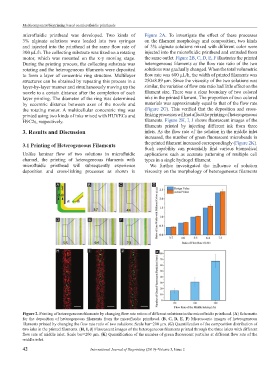
microfluidic printhead was developed. Two kinds of Figure 2A. To investigate the effect of these processes
3% alginate solutions were loaded into two syringes on the filament morphology and composition, two kinds
and injected into the printhead at the same flow rate of of 3% alginate solutions mixed with different color were
300 µL/h. The collecting substrate was fixed on a rotating injected into the microfluidic printhead and extruded from
motor, which was mounted on the x-y moving stage. the same outlet. Figure 2B, C, D, E, F illustrates the printed
During the printing process, the collecting substrate was heterogeneous filaments as the flow rate ratio of the two
rotating and the heterogeneous filaments were deposited solutions was gradually changed. When the total volumetric
to form a layer of concentric ring structure. Multilayer flow rate was 600 µL/h, the width of printed filaments was
structures can be obtained by repeating this process in a 250±8.89 µm. Since the viscosity of the two solutions was
layer-by-layer manner and simultaneously moving up the similar, the variation of flow rate ratio had little effect on the
nozzle to a certain distance after the completion of each filament size. There was a clear boundary of two colored
layer printing. The diameter of the ring was determined inks in the printed filament. The proportion of two colored
by eccentric distance between axes of the nozzle and materials was approximately equal to that of the flow rate
the rotating motor. A multicellular concentric ring was (Figure 2G). This verified that the deposition and cross-
printed using two kinds of inks mixed with HUVECs and linking processes will not affect the printing of heterogeneous
H9C2s, respectively. filaments. Figure 2H, I, J shows fluorescent images of the
filaments printed by injecting different ink from three
3. Results and Discussion inlets. As the flow rate of the solution in the middle inlet
increased, the number of green fluorescent microbeads in
3.1 Printing of Heterogeneous Filaments the printed filament increased correspondingly (Figure 2K).
Such capability can potentially find various biomedical
Unlike laminar flow of two solutions in microfluidic applications such as accurate patterning of multiple cell
channel, the printing of heterogeneous filaments with types in a single hydrogel filament.
microfluidic printhead will subsequently experience We further investigated the influence of solution
deposition and cross-linking processes as shown in viscosity on the morphology of heterogeneous filaments
A B C G
D E F
H I J K
Figure 2. Printing of heterogeneous filaments by changing flow rate ration of different solutions in the microfluidic printhead. (A) Schematic
for the deposition of heterogeneous filaments from the microfluidic printhead. (B, C, D, E, F) Microscopic images of heterogeneous
filaments printed by changing the flow rate ratio of two solutions. Scale bar=200 µm. (G) Quantification of the composition distribution of
two inks in the printed filaments. (H, I, J) Fluorescent images of the heterogeneous filaments printed through the three inlets with different
flow rate of middle inlet. Scale bar=200 µm. (K) Quantification of the number of green fluorescent particles at different flow rate of the
middle inlet.
42 International Journal of Bioprinting (2019)–Volume 5, Issue 2