
Page 59 - IJB-6-4
P. 59
Bishop and Leigh
seen in the sliced file in Figure 3B. An example print is generated through the additive slicer
of the final print can be seen in Figure 3C. The used for LSAM, by taking a solid and extracting
preparation of the designs for printing was carried the outermost perimeters. Thus, the headband
out in Simplify 3D and printing was carried out design was modified to create a fully solid design
using a 3D Platform Workbench system. This (Figure 4A), with the slicer software generating
version of the design took just 5 min to print. The the required toolpath (Figure 4B). The resulting
nature of the printing method meant that the seam headband was printed in 4 min. The most notable
line (from the start and stop point of the layers) impact of using this strategy is that the visible
led to defects in the final print (as can be seen on seam line and defects are completely removed,
the strap attachment point), meaning some hand thereby removing the requirement for any hand
finishing was required. finishing (Figure 4C).
3.2 Design iteration (version 2) 3.3 Speeding up the manufacturing
process/sequential deposition for quality
While the initial design worked, the clear lens/visor
which is held on at 4 points, did not hold on very To speed up the manufacturing process and ensure
well, as the lip which can be found in many of continued part quality (crucial for scaling up
the small scale designs needed to be removed production), the use of a sequential manufacturing
for LSAM to be possible. The headband was strategy was employed. In a conventional additive
therefore redesigned to change the two outer two manufacturing process, when producing multiple
attachment pins into hooks which could be printed parts on a single print bed, all the parts will be
with the 1.8 mm nozzle which vastly improved produced in parallel such that the layers of each
the design. At this point, it was also decided to are incremented at the same time. Producing parts
change the design to allow for “vase mode” to in this way leads to lots of non-print travel moves
be employed (toolpath optimization) vase mode (red lines), as can be seen in the toolpath preview
is where the printhead moves continuously in in Figure 5A. Printing multiple parts on a single
Z throughout the print, varying the Z parameter print bed using traditional parallel printing with
slightly, in contrast to printing a single layer, at FFF systems can result in defects on the parts, such
constant Z value, stopping in XY and then moving as stringing that can occur when material exits the
to the next layer. The toolpath for a “vase mode” nozzle during non-print moves between parts [27,28] .
A B
C
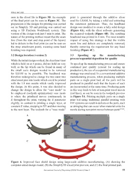
Figure 4. Improved face shield design using large-scale additive manufacturing, (A) showing the
computer-aided design model, (B) the Simplify3D sliced print preview, and (C) the final printed part.
International Journal of Bioprinting (2020)–Volume 6, Issue 4 55