
Page 577 - IJB-10-6
P. 577
International Journal of Bioprinting Biomechanical analysis of mandibular implants
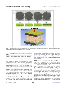
Figure 1. The finite element analysis (FEA) of 3D titanium alloy lattice models: (a) the 3D porous structures of four different lattice models and (b)
the loading and boundary conditions applied to the FE lattice model.
Table 1. Material properties of the finite element (FE) lattice 1 mm/min until the yield point of each sample was reached
model. (Figure 3). To determine the elastic modulus of the three
lattice rod diameters, the load force and displacement data
Material Elastic modulus (MPa) Poisson’s ratio Reference were recorded to plot a stress–strain curve and calculate its
Ti6Al4V 96,000 0.36 21
slope (Figure 4).
were selected. A ZRapid iSLM280 metal 3D printer 2.4. Designing a customized mandibular model
(ZRapid Technologies, China) was used to print the This study was approved by the Institutional Review
3D titanium alloy lattice models required for in vitro Board of the China Medical University Hospital (approval
compression experiments (Figure 2). To ensure the no. CMUH110-REC2-247). Cone-beam computed
quality of 3D printing, the production speed was set tomography images were obtained from the mandible
to 4 cm³/h; the printing layer thickness was 0.02 mm. of a patient with a right-sided malignant tumor. The
Additionally, all samples underwent sandblasting and images were imported into the medical imaging software
fine sandpaper polishing to make the lattice interior and Mimics (version 14.0; Materialise, Belgium) to obtain
cubit surface smoother. Each set included three distinct the mandible’s outline and the contours of cortical and
cancellous bone based on grayscale intensity values. The
lattice rod diameters (0.5, 0.7, and 0.9 mm), with five resulting data were exported as STL files and imported
samples per set.
into the reverse-engineering software SpaceClaim (Ansys,
After the 3D-printed titanium alloy lattice samples were USA) to reconstruct the 3D surface mesh of the mandible.
placed on the platform of an MTS QTest/10 load frame Subsequently, the data were imported into the computer-
(MTS Systems, USA), axial pressure was applied at a rate of aided design software SolidWorks 2024 (Dassault Systèmes
Volume 10 Issue 6 (2024) 569 doi: 10.36922/ijb.3943