
Page 580 - IJB-10-6
P. 580
International Journal of Bioprinting Biomechanical analysis of mandibular implants
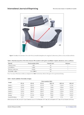
Figure 5. Simulated finite element (FE) model of the (a) mandibular implant with wing plate, (b) abutment, (c) bone screws, and (d) mandibular.
Table 2. Material properties of the finite element (FE) models involving the mandibular implant, abutment, screws, and bone.
Material Elastic modulus (MPa) Poisson’s ratio Reference
Trabecular bone 1600 0.3 22
Cortical bone 14,800 0.3 22
Abutment and screws 110,000 0.35 22
Mandibular implant From Table 3 0.3
Note: The values of the elastic modulus are adapted from Table 3, which were obtained through in vitro experimental testing.
Table 3. Elastic modulus of six lattice designs.
Elastic modulus (MPa)
Sample
HV-d1 HV-d2 HV-d3 QDC-d1 QDC-d2 QDC-d3
Sample 1 1247.50 2226.67 2253.59 773.08 1720.69 2175.43
Sample 2 1254.40 1999.00 2349.18 768.46 1705.64 2191.63
Sample 3 1251.30 2072.27 2288.51 763.08 1683.56 2178.26
Sample 4 1242.50 2064.85 2280.57 768.46 1758.86 2187.47
Sample 5 1171.80 2216.11 2254.21 669.33 1726.21 2212.33
Average 1233.50 2115.80 2285.20 748.48 1719.00 2189.03
Standard deviation 34.77 100.61 39.00 44.39 27.74 14.60
Abbreviations: HV: Hex-vase; QDC: Quad-diametral-cross; d1: Rod diameter of 0.5 mm; d2: Rod diameter of 0.7 mm; d3: Rod diameter of 0.9 mm.
Volume 10 Issue 6 (2024) 572 doi: 10.36922/ijb.3943