
Page 579 - IJB-10-6
P. 579
International Journal of Bioprinting Biomechanical analysis of mandibular implants
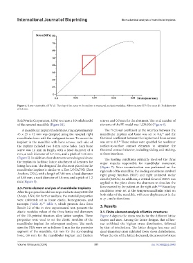
Figure 4. Stress–strain plot of HV-d1. The slop of the curve in the red box is measured as elastic modulus. Abbreviations: HV: Hex-vase; d1: Rod diameter
of 0.5 mm.
SolidWorks Corporation, USA) to create a 3D solid model screws, and 0.5 mm for the abutment. The total number of
of the resected mandible (Figure 5d). elements of the FE model was 1,238,926 (Figure 6).
A mandibular implant model measuring approximately The frictional coefficient at the interface between the
45 × 35 × 12 mm was designed using the resected right mandibular implant and bone was set to 0.4, and the
23
mandibular bone with the malignant tumor. To secure the frictional coefficient between the implant and bone screws
24
implant in the mandible with bone screws, each side of was set to 0.3. These values were specified for nonlinear
the implant included two 4-mm screw holes. Each bone surface-to-surface contact elements to simulate the
screw was 12 mm in length, with a head diameter of 4 frictional contact behavior, including sliding and sticking,
mm, a neck diameter of 2.7 mm, and a pitch of 1.26 mm at these interfaces.
(Figure 5). In addition, four abutments were designed above The loading conditions primarily involved the three
the implant to facilitate future attachment of dentures for major muscles responsible for mandibular movement
biting function. The design of the abutment placed on the (Figure 7). Since reconstruction was performed on the
mandibular implant is similar to a Zest LOCATOR (Zest right side of the mandible, the loading conditions involved
Anchors, USA), with a length of 7.88 mm, a head diameter right group function (RGF) and right unilateral molar
of 3.86 mm, a neck diameter of 1.8 mm, and a pitch of 1.2 clench (RMOL). In addition, a vertical force of 100 N was
mm (Figure 5). applied to the plane above the abutment to simulate the
2.5. Finite element analysis of mandibular implants force exerted by the patient on the right side. 25,26 Boundary
After the proposed model was imported into Ansys 2021 R2 conditions were set at the temporomandibular joint on
(Ansys, USA) for further analysis, the material properties both sides of the mandible, with zero displacement in the
were uniformly set as linear elastic, homogeneous, and x-, y-, and z-directions.
isotropic (Table 2). Table 3, which presents data from
22
Result 3.2 of the in vitro experimental test, presents the 3. Results
elastic modulus values of the three lattice rod diameters 3.1. Finite element analysis of lattice structures
of the 3D-printed titanium alloy lattice samples. These Figure 8 depicts the stress results for the different lattice
properties were used to set the elastic modulus of the shapes and sizes. Among the lattice designs, that of hex-
mandibular implant for subsequent analyses. The mesh star exhibited the highest stress distribution, followed
sizes for FEA were set as follows: 1 mm for the posterior by that of tetrahedron. The lattice designs hex-vase and
segment of the mandible, 0.8 mm for the surrounding quad-diametral-cross exhibited lower stress distributions.
bone, 0.6 mm for the mandibular implant and fixation When the size of the lattice decreased, the amount of stress
Volume 10 Issue 6 (2024) 571 doi: 10.36922/ijb.3943