
Page 581 - IJB-10-6
P. 581
International Journal of Bioprinting Biomechanical analysis of mandibular implants
Figure 6. Mesh status of the finite element model of the mandibular implant.
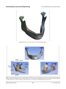
Figure 7. Loading and boundary conditions of the finite element (FE) model. The blue section represents the fixed area and the red section represents the
loading position of the mandibular muscle. A: Superficial masseter; B: Deep masseter; C: Medial pterygoid; D: Anterior temporalis; E: Middle temporalis;
F: Posterior temporalis; G: Posterior temporalis; H: Superficial masseter; I: Deep masseter; J: Medial pterygoid; and N: Fixation.
Volume 10 Issue 6 (2024) 573 doi: 10.36922/ijb.3943