
Page 73 - IJB-7-1
P. 73
Jing, et al.
A B
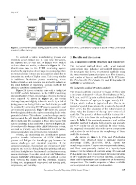
Figure 1. Electrohydrodynamic printing (EHDP) system and scaffold fabrication. (A) Schematic diagram of EHDP system. (B) Scaffold
structure by fiber stacking.
To establish a viable manufacturing process and 3. Results and discussion
minimize defect-related loss in long time fabrication,
the captured EHDP cone and jet images were applied 3.1. Composite scaffold structure and tensile test
to detect abnormal modes, as shown in Figure 2A. The The fabricated scaffold fibers with varied material
identification task in this EHDP monitoring system compositions may influence cell-scaffold interactions.
involves the application of an image processing algorithm To investigate this factor, we prepared scaffolds using
to extract relevant features and a recognition algorithm to the same structural parameters (pore size, fiber diameter,
determine the modes of Taylor cones. This is very similar and number of layers), and fabricated PCL, PCL/zein-
to traditional fabrication process monitoring, where 10, PCL/zein-20, PCL/gliadin-10, and PCL/gliadin-20
feature extraction and selection are applied to determine scaffolds for comparison.
the input features of machining learning methods for
effective condition identification [24,25] . (1) Composite scaffold structure analysis
Figure 2B shows a standard cone with a straight jet
for EHDP scaffold fabrication. In the EHDP monitoring The printed scaffolds consist of 12 layers of fibers with
and identification system, various types of corona discharge a thickness of about 65 – 85 μm. The thickness of PCL,
were reported. As shown in Figure 2C, the corona PCL/zein, and PCL/gliadin scaffolds is stated in Table 1.
discharge happened slightly below the needle tip at initial The fiber diameter of top layer is approximately 8.9 –
jetting process or during fabrication. Such discharge could 9.4 μm, which is close to typical cell size. Due to the
be avoided by optimizing EHDP process parameters and impact of ejected filament onto the previously deposited
environmental parameters. Figure 2D shows the current fiber layers, the fiber diameter of the bottom layers is
flow through the air from the region surrounding the jet to the about twice the diameter of the top layer cross of all
grounded substrate. This reduced the surface charge density scaffolds. The porosity of these scaffolds is about 89 –
and increased the jet’s lateral stability. Different from the 92.1%, which is in favor for exchanging nutrition and
above-mentioned two scenarios, a huge Taylor cone with waste. In Table 1, the structural parameters such as fiber
serious discharge at the needle tip is shown in Figure 2E. diameter, scaffold thickness, bulk density, and porosity
To avoid possible damages of the EHDP fabrication system, are very similar for all the scaffolds. In other words,
we need to properly vary the biomaterial ink properties, the proposed biomaterial inks with current components
process parameters, and environmental parameters. and portion do not influence the morphology of these
Overall, this monitoring and identification system scaffolds obviously.
provides intuitive information of EHDP fabrication As shown in Figure 3, PCL and PCL/gliadin
process and bridges the knowledge gap between the scaffolds were observed using a scanning electron
corona discharges and electrical properties of the microscope (SEM, JSM-6510, JEOL, Japan) for
composite materials. Researchers can evaluate new inks’ morphology analysis. The pore size was precisely defined,
property and stability during long time printing and gain and fibers were precisely stacked in a layer-by-layer
additional insights into fundamental mechanism causing manner. For the fabricated scaffolds using PCL/zein and
corona discharges. It can also assist new inks’ fabrication PCL/gliadin inks, there was not much difference in terms
process parameter optimization such as applied electric of fiber diameter and cross-section structure. In general,
field between the nozzle and the substrate, solution these scaffold parameters are independent of the material
feeding rate, programmed stage speed and moving path, compositions. The tensile properties of these scaffolds
temperature, and humidity. were compared and analyzed in sub-section.
International Journal of Bioprinting (2021)–Volume 7, Issue 1 69