
Page 117 - IJB-7-3
P. 117
Li, et al.
A B
C
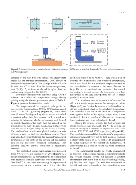
Figure 3. Schematic of nozzle exposed in the air with flowing hydrogel. (A) The temperature distribution. (B) The stress on the microelement.
(C) Printing process.
direction of the heat flow will change. The steady-state coefficient was set to 50 W/m °C. There was a good fit
2
means that the extrudate temperature, T , will always be between the experimental and predicted temperatures,
E
between the temperatures of the syringe and the AT, that and it was found that the extrudate temperature rose as
is, when the AT is lower than the syringe temperature, the controlled nozzle temperature increased. Because the
then T ≥ T ≥ T , while when the AT is higher than the large ID nozzle contained more materials that carried
c
E
A
syringe temperature, then T ≥ T ≥ T . the syringe’s thermal energy, the temperature was less
N
E
A
Four sets of analyses were conducted using ANSYS susceptible to the AT; consequently, the 23-G nozzle
software to explore the temperature change during produced a steeper slope.
printing using the thermal parameters given in Table 1. The model was used to explore the influence of the
Figure 4 presents the simulation results. AT on the steady temperature of the hydrogel extrudate
The temperature of the composite hydrogel in the (Figure 4D), and the simulation results confirmed that the
nozzle center increased from 21°C to 31°C and decreased AT had a significant effect on the extrudate’s temperature.
from 21°C to 19°C gradually (Figure 4B). After more The influence of the AT on the extrudate’s temperature
than 40 min of heating/cooling, the temperature reached was opposite to that of the syringe temperature. It was
a constant value; this phenomenon could be used as a confirmed that the smaller (32-G) nozzle containing
criterion to determine whether a bioink is well heated fewer materials was more vulnerable to the AT.
or cooled. Because of the slight heat loss caused by the During the printing process, the flow of materials
exposed nozzle, the hydrogel’s steady stage in the syringe inside the nozzle was affected by the AT. To explore the
was not affected significantly by the nozzle’s scaling. transient change of the material’s temperature, the AT was
The results of one nozzle were plotted, and several sets set to 19°C, 27°C, and 32°C, respectively (Figure 4E).
of experiments verified the simulation results. There The simulation revealed that the extrudate’s temperature
was a good agreement between the hydrogel’s measured responses were relatively fast for both nozzles, reaching
temperature in the center of the syringe and the heating a steady-state within 10 s. A smaller ID corresponded
and cooling processes’ predicted temperature. This to faster response in the simulation; furthermore, it
confirms that the thermal simulation is reasonably demonstrated that a smaller nozzle was more vulnerable
accurate. to the AT.
The controlled syringe temperature was increased The experimental results are briefly summarized
from 19°C to 31°C at a constant AT of 20°C (Figure 4C), as follows: (a) The central material’s temperature inside
and the temperature of the extrudate at the tip of the nozzle the syringe changed slowly and reached a constant
was measured. The film coefficient was determined (5 – temperature after more than 40 min of heating/cooling,
200 W/m °C in the native flow) using the experimental (b) Nozzles with larger IDs were less susceptible to
2
temperatures of the extrudate. After fitting, the film the AT and more vulnerable to the controlled syringe
International Journal of Bioprinting (2021)–Volume 7, Issue 3 113