
Page 119 - IJB-7-3
P. 119
Li, et al.
and uniformity of the printed outcome [40,42,43] . This section 1 1 1
explores the influence of temperature, pressure, and P n R n 1 r n 1 and (11)
velocity on printability (as represented by linewidth). ur() 2 kL 1
Both the power-law model and the die-swell phenomenon n 1
were considered before establishing a physical model for
the a priori prediction of the linewidth. R R PR 1 n
3
u r
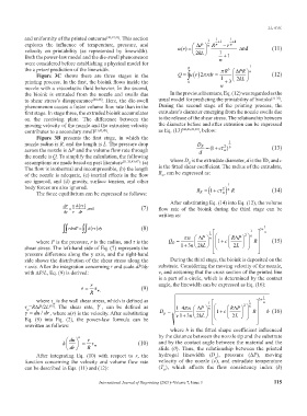
Figure 3C shows there are three stages in the Q 2 rdr (12)
printing process. In the first, the bioink flows inside the 0 1 3 2 kL
nozzle with a viscoelastic fluid behavior. In the second, n
the bioink is extruded from the nozzle and swells due In the previous literature, Eq. (12) was regarded as the
to shear stress’s disappearance [44-48] . Here, the die-swell usual model for predicting the printability of bioinks [31-33] .
phenomenon causes a faster volume flow rate than in the During the second stage of the printing process, the
first stage. In stage three, the extruded bioink accumulates extrudate’s diameter emerging from the nozzle swells due
on the receiving plate. The difference between the to the release of the shear stress. The relationship between
moving velocity of the nozzle and the extrusion velocity the diameter before and after extrusion can be expressed
contributes to a secondary swell [31,43,49] . as Eq. (13) [44,46,49,50] , below:
Figure 3B presents the first stage, in which the
nozzle radius is R, and the length is L. The pressure drop D E 1 (13)
across the nozzle is ∆P and the volume flow rate through d (1 c w 2 6
)
the nozzle is Q. To simplify the calculation, the following
assumptions are made based on past literature [31,33,43,47] : (a) where D is the extrudate diameter, d is the ID, and c
E
The flow is isothermal and incompressible, (b) the length is the fitted shear coefficient. The radius of the extrudate,
of the nozzle is adequate, (c) inertial effects in the flow R , can be expressed as:
E
are ignored, and (d) gravity, surface tension, and other
body forces are also ignored. 2 6 1 R (14)
c
The force equilibrium can be expressed as follows: R 1 w
E
After substituting Eq. (14) into Eq. (12), the volume
dP 1 dr (7) flow rate of the bioink during the third stage can be
dy r dr ,and
written as:
rdrdP d r dy (8) 1 1 3 3 1 n
n P 2 6
RP
n
where P is the pressure, r is the radius, and τ is the Q 1 c R (15)
E
shear stress. The left-hand side of Eq. (7) represents the 13 n 2 kL 2 L
pressure difference along the y axis, and the right-hand
side shows the distribution of the shear stress along the During the third stage, the bioink is deposited on the
r axis. After the integration concerning r and scale dP/dy substrate. Considering the moving velocity of the nozzle,
with ∆P/L, Eq. (9) is derived: v, and assuming that the cross section of the printed line
is a part of a circle, which is determined by the contact
r angle, the linewidth can be expressed as Eq. (16):
(9)
R w,
where τ is the wall shear stress, which is defined as 1 3 1 n
w
1
τ =R∆P/2L . The shear rate, γ , can be defined as 14 n P 2 6
[49]
RP
n
w
du dr/ , where u(r) is the velocity. After substituting D v kL 1 c L R b (16)
p
Eq. (9) into Eq. (2), the power-law formula can be 13 n 2 2
rewritten as follows:
where b is the fitted shape coefficient influenced
du n r by the distance between the nozzle tip and the substrate
k w (10) and by the contact angle between the material and the
dr R slide (θ). Thus, the relationship between the printed
After integrating Eq. (10) with respect to r, the hydrogel linewidth (D ), pressure (∆P), moving
p
function concerning the velocity and volume flow rate velocity of the nozzle (v), and extrudate temperature
can be described in Eqs. (11) and (12): (T ), which affects the flow consistency index (k)
E
International Journal of Bioprinting (2021)–Volume 7, Issue 3 115