
Page 53 - IJB-7-4
P. 53
Lin, et al.
and in vivo experiments showed that new osteogenesis to determine the optimal printing parameters, selecting a
could be observed on PCL+β-TCP, PCL+ β-TCP+M rod structure with a pore size at 600 μm to maintain the
scaffolds, and the largest area of new osteogenesis was properties of most raw material, and the experimental
observed on the PCL+β-TCP+M scaffolds. results showed that the scaffold promoted the proliferation
of bone marrow stromal cells in vitro and could be
3.2. Double layer structure incubated for 7 days with significantly higher levels of
osteogenic gene transcription than the blank control.
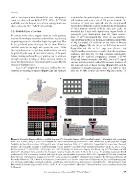
In contrast to the classic support structure in the previous Shao et al. [91] investigated the effect of one-step/two-
section, the two-layer structure can be realized by adjusting step sintering method on the physicochemical properties
the printing parameters based on single-layer printing. That of Mg ion-doped CS scaffolds on the basis of bilayer
is, the printhead prints two layers in the same direction printing (Figure 2B), the bilayer scaffolds had increased
and then switches the angle and repeats the print. Unlike degradation rate due to their large pore diameter but
the single-layer structure printing, multi-material can only slightly weaker compressive properties than the monolayer
be printed by the way of mechanical mixing of the paste scaffolds, and then the two-step sintering significantly
before printing, and double-layer printing can be achieved improved the scaffold compressive strength (~25104
through multi-jet printing or direct stacking method to MPa) and flexural strength (~618 MPa). Jin et al. doped
[92]
avoid the degradation of material properties caused by the calcium silicate powders with different mass fractions of
mixing of multiple pastes. Mg ions and used a bilayer printing (Figure 2C), and its
Lin et al. prepared a COL-HA scaffold by low- compressive strength increased from 11.2 MPa to 39.4
[5]
temperature printing technique (Figure 2A) and analyzed MPa and 80 MPa with the increase of Mg ions content. To
A C
D
B
E
Figure 2. Schematic diagram of bilayer scaffold structure. (A) Schematic diagram of CHA scaffold printing . (Reprinted with permission
[5]
from Lin K F, He S, Song Y, et al. Low-Temperature Additive Manufacturing of Biomimic Three-Dimensional Hydroxyapatite/Collagen
Scaffolds for Bone Regeneration. ACS Applied Materials and Interfaces. 2016; 8(11):6905-6916. Copyright© 2016 American Chemical
Society). (B) Schematic diagram of scaffold printing by LBL method . Reprinted with permission from Shao H, Ke X, Liu A, et al.,
[91]
Biofabrication,2017; 9(2):025003, ©Copyright 2021 IOP Publishing (C) Schematic diagram of cell-carrying α-TCP/collagen scaffold
printing . (Reprinted from Journal of the European Ceramic Society, 36, Shao H, He Y, Fu J, et al., 3D printing magnesium-doped
[92]
wollastonite/β-TCP bioceramics scaffolds with high strength and adjustable degradation, 1495-1503, Copyright (2016) with permission
from Elsevier). (D) Schematic diagram of CSi+PVA+Metal ion bilayer scaffold . (Reprinted from Journal of the Mechanical Behavior of
[93]
Biomedical Materials, 104, Alksne M, Kalvaityte M, Simoliunas E, et al. In vitro comparison of 3D printed polylactic acid/hydroxyapatite
and polylactic acid/bioglass composite scaffolds: Insights into materials for bone regeneration, Copyright© 2021, with permission from
Elsevier) (E) Schematic diagram of PLA/PLA+HA/PLA+BG bilayer scaffold . (From ref. licensed under Creative Commons Attribution
[94]
[94]
4.0 license).
International Journal of Bioprinting (2021)–Volume 7, Issue 4 49