
Page 96 - IJB-8-2
P. 96
3D-printed Stent Coated with Dipyridamole-loaded Nanofiber
A
B C
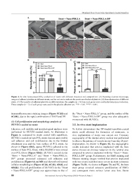
Figure 4. In vitro hemocompatibility evaluation of stents with different structures and compositions. (A) Scanning electron microscopy
images of adhered platelets on different stents, and the red circles indicate the positions of adhered platelets. (B) Hemolysis ratios of different
stents. (C) The number of adherent platelets on different stents. Six samples (n = 6) from each group were used in the hemolysis evaluation.
Three samples (n = 3) of each group were used in the platelet adhesion test. **P < 0.01. ***P < 0.001.
immunofluorescence staining images (Figure 5C(iii) and the “Stent + Nano-PDLLA” group, and the surface of the
6C(iii)), due to the rapid combination of DAPI and DP. “Stent + Nano-PDLLA-DP” group was also adequately
overspread with HUVECs.
(3) Cell proliferation and morphology analysis of
HUVECs seeded on stents 3.5. In vivo stent implantation
Likewise, cell viability and morphological analyses were To further demonstrate that DP-loaded nanofiber-coated
performed for HUVEC-seeded stents. As illustrated in stents could alleviate the formation of restenosis, in
Figure 6, compared to stents coated with nanofibers, vivo implantation of stents was carried out. Coronary
HUVECs seeded on bare PCL stents showed unfavorable angiography of the stented artery section was performed
cell adhesion and cell proliferation due to the limited to observe the patency of vessels on day 0 and day 28 post-
attachment area and the bare surface of PCL struts. As implantation. As shown in Figure S6, the angiographic
shown in Figure 6D(i), sparse HUVECs adhered to the results indicated that arteries implanted with the bare
surface of bare PCL fibers, while RASMCs were spread stents showed an obvious reduction in the luminal area
over PCL fibers (Figure 5D(i)). HUVECs seeded on the compared to arteries implanted with the “Stent + Nano-
“Stent + Nano-PDLLA” and “Stent + Nano-PDLLA- PDLLA-DP” group. Furthermore, the H&E staining and
DP” groups presented enhanced cell adhesion and Masson staining images verified that arteries implanted
proliferation (Figure 6A and 6B) and showed well-spread with bare stents exhibited more severe in-stent restenosis
cellular morphologies (Figure 6C(ii), 6C(iii), 6D(ii), and (Figure 7A-D). As shown in Figure 7A and 7C, the bare
6D(iii)). The cell proliferation of HUVECs in the “Stent stent group revealed extensive proliferation of SMCs
+ Nano-PDLLA-DP” group was approximate to that of and consequent more serious lumen area loss. Stents
88 International Journal of Bioprinting (2022)–Volume 8, Issue 2