
Page 118 - IJB-8-4
P. 118
3D Bioprinting of Osteotomy-Aided Module
Table 1. Material properties of Sawbones.
(A) Simulated cortical bone (short fiber‑filled epoxy)
Density (g/cm ) Longitudinal tensile Transverse tensile Compressive
3
Strength Modulus Strength Modulus Strength Modulus
(MPa) (GPa) (MPa) (GPa) (MPa) (GPa)
1.64 106 16.0 93 10.0 157 16.7
(B) Simulated cancellous bone (rigid polyurethane foam)
Density (g/cm ) Strength (MPa) Modulus (GPa)
3
0.32 106 16.0
A B
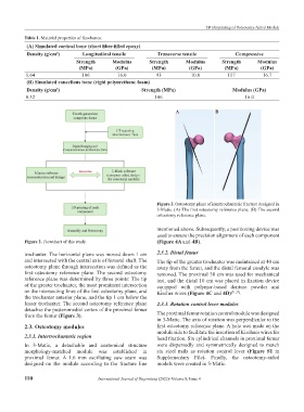
Figure 3. Osteotomy plane of intertrochanteric fracture designed in
3-Matic. (A) The first osteotomy reference plane. (B) The second
osteotomy reference plane.
mentioned above. Subsequently, a positioning device was
used to ensure the precision alignment of each component
Figure 2. Flowchart of this study. (Figure 4A and 4B).
trochanter. The horizontal plane was moved down 1 cm 2.3.2. Distal femur
and intersected with the central axis of femoral shaft. The The tip of the greater trochanter was maintained at 40 cm
osteotomy plane through intersection was defined as the away from the femur, and the distal femoral condyle was
first osteotomy reference plane. The second osteotomy removed. The proximal 30 cm was used for mechanical
reference plane was determined by three points: The tip test, and the distal 10 cm was placed in fixation device
of the greater trochanter, the most prominent intersection equipped with polymer-based denture powder and
on the intersecting lines of the first osteotomy plane, and Kircher wires (Figure 4C and 4D) [21,22] .
the trochanter anterior plane, and the tip 1 cm below the
lesser trochanter. The second osteotomy reference plane 2.3.3. Rotation control lever modules
detaches the posteromedial cortex of the proximal femur
from the femur (Figure 3). The proximal femur rotation control module was designed
in 3-Matic. The axis of rotation was perpendicular to the
2.3. Osteotomy modules first osteotomy reference plane. A hole was made on the
module side to facilitate the insertion of Kirchner wires for
2.3.1. Intertrochanteric region head fixation. Six cylindrical channels in proximal femur
In 3-Matic, a detachable and anatomical structure were dispersedly and symmetrically designed to match
morphology-matched module was established in six steel nails as rotation control lever (Figure S1 in
proximal femur. A 1.6 mm oscillating saw seam was Supplementary File). Finally, the osteotomy-aided
designed on the module according to the fracture line models were created in 3-Matic.
110 International Journal of Bioprinting (2022)–Volume 8, Issue 4