
Page 31 - IJB-8-4
P. 31
Microsphere-Based Bioink for Large Tissue with Angiogenesis
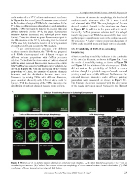
and transferred to a 37°C culture environment. As shown In terms of microscale morphology, the incubated
in Figure 4A, the area of green fluorescence concentrated centimeter-scale structures after 24 h were treated
in the location of original TSMs before incubation. At the and observed with SEM. The morphologies of the on-
5 h, the green fluorescence intensity decreased, indicating demand nutrient channels in the structures are shown
th
that the TSMs has begun to transfer to solation state and in Figure 4C. In addition to the pores with microscale
diffuse outwards. At the 10 h, the green fluorescence formed by GelMA precursor solution itself, the sol-gel
th
intensity further decreased and spherical pores were transferring process of TSMs has successfully form more
formed. There was almost no green fluorescence signal in and larger pores in millimeter scale in the centimeter-scale
the 3D structure at the 24 h, indicating that the internal 3D structures. A higher volume proportion diameters of
th
TSMs have fully finished the mission of forming nutrient TSMs could establish more and larger nutrient channels.
channels and diffused outside the 3D structure.
To get centimeter-scale structures with different 3.5. Printability of TSM-B in extruding
nutrient channels distribution, the TSM-B was prepared bioprinting
with TSMs electrosprayed with different voltages at
different volume proportions with GelMA precursor A basic extruding printability indicator is the continuity
solution. To facilitate the observation of nutrient channel of the extruded filament, as shown in Figure 5A. From
patterns under confocal fluorescence microscope, a little the results of printability testing, as shown in Figure 5B
GFP-GelMA was added to GelMA precursor solution. As and Figure S5, the addition of the electrosprayed TSMs
shown in Figure 4B, with the increasing of the volume did not restrict the printability of GelMA precursor
proportions of TSMs, the quantity of nutrient channels solution, though the printable ranges of nozzle size and
increased and the distribution became more even. printing speed were a little different. Furthermore, the
Moreover, by mixing TSMs with different diameters, extruded filament diameters under different printing
pores (nutrient channels) with different sizes could be parameters were measured, as shown in Figure 5C.
formed. With the decreasing of the TSMs diameters, the The filament diameters increased with the decreasing
distribution of nutrient channels became more uniform. of the nozzle movement speed. Noticeably, the filament
A
B C
Figure 4. Morphology of on-demand nutrient channels in centimeter-scale structure. (A) Solation transferring process of the TSMs in
the culturing environment. (B) Confocal fluorescence microscope morphology of the on-demand nutrient channels distribution. (C) SEM
morphology of the on-demand nutrient channels distribution.
International Journal of Bioprinting (2022)–Volume 8, Issue 4 23