
Page 73 - IJB-9-1
P. 73
International Journal of Bioprinting Osteoconduction and scaffold directionality
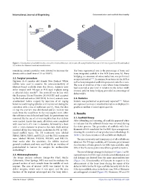
Figure 1. Construction of scaffold from the unit cell to microarchitecture. (A) A unit cell exemplified for filaments of 0.5 mm is patterned (B) and stacked
(C) to form the filament-based microarchitecture.
remaining ceramic particles were sintered to increase the The bony regenerated area is the percentage of bone and
density with a dwell time of 3 h at 1100°C. bony integrated scaffold in the AOI (bony area, %). Bony
bridging, as a measure of osteoconduction, was performed
2.2. Surgical procedure as reported earlier [2,31] . In essence, bone tissue in the AOI as
Eighteen (6–8 months old) female New Zealand White well as bony integrated scaffold is projected onto the x-axis.
rabbits were used to examine the osteoconductivity of The sum of stretches of the x-axis where bone formation
filament-based scaffolds from this library. Animals were had occurred at any level in relation to the defect width
either treated with Fil-type or FilG-type implants using (6 mm) yield in bony bridging provided as percentage of
[2]
a calvarial defect model . The protocol was in line with defect width.
the European Union Directive 2010/63/EU and accepted
by the local authorities (065/2018). In brief, animals were 2.4. Statistics
anesthetized before surgery by injection of 65 mg/kg Statistic was performed as previously reported [2,31] . Values
ketamine and 4 mg/kg xylazine and maintained during the are expressed as mean ± standard deviation or displayed in
operation with a mix of isoflurane and O . Next, the skin graphs as median ± lower/upper quartile.
2
on top the cranium was disinfected and an incision was
made from the nasal bone to the mid-sagittal crest. After 3. Results
the soft tissue was deflected and fixed, the periosteum was
removed. By the use of a 6-mm trephine bur, four defects 3.1. Scaffold library
were marked. Inside this mark, all defects were completed After debinding and sintering, all scaffolds appeared white
with rose burrs of 5 mm in diameter, followed by a burr to indicate that the yellowish binder was removed during
with a 1 mm diameter to preserve the dura. Each animal the sinter process. The generation of scaffolds with finer
received all the four treatment modalities for Fil- or FilG- filaments of 0.35 mm failed for the FilG-type arrangement,
based scaffold types. The Fil treatments were labeled showing the constrains of our production methodology. In
Fil040, Fil050, Fil083, and Fil125, and the FilG treatments Table 1, the characteristics of all scaffolds are displayed.
were labeled FilG040, FilG050, FilG083, and FilG125. The macroporosity and transparency of all scaffolds are
Four weeks after the operation, the rabbits received identical. For Fil-type scaffolds, all filaments point toward
general anesthesia and were sacrificed by an overdose of the direction of bone growth; for FilG-type scaffolds, only
pentobarbital to harvest the samples for methacrylate 50% of the filaments point toward bone growth direction.
embedding .
[2]
The overall design strategy is displayed in Figure 2 as Fil-
2.3. Histomorphometry type and respective FilG-type of identical rod dimension and
The image analysis software (Image-Pro Plus®; Media rod distance are derived from the same microarchitecture
Cybernetic, Silver Springs, MD) was used to evaluate the (Figure 2A). Directionality of filaments in respect to the
ground section of each sample from the middle of each advancement of the bone front during the repair of the
implant. The area of interest (AOI) was limited by the defect is 100% for the Fil-type scaffolds but only 50% for the
defect margins, which were 6 mm apart, and the area FilG-type scaffolds, since in the latter case, 50% of filaments
fraction of the implant submerged into the bony defect. are orthogonal oriented (Figure 2B). Moreover, 3D and 2D
V
Volume 9 Issue 1 (2023)olume 9 Issue 1 (2023) 65 https://doi.org/10.18063/ijb.v9i1.626